Author: admin

  • Solar Panel And MPPT Controller Connection Wiring For Off-grid Power

    Solar Panel And MPPT Controller Connection Wiring For Off-grid Power

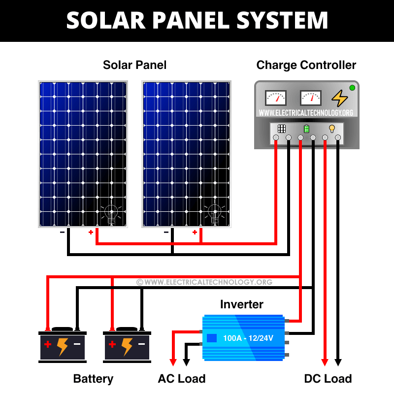
    “Solar panel and MPPT controller connection wiring for off-grid power

    The use of solar panels and Maximum Power Point Tracking (MPPT) controllers has made it possible to harness the sun’s energy and convert it into electrical power. However, the connection wiring between solar panels and MPPT controllers is crucial to ensure efficient and safe operation. In this article, we will provide a comprehensive guide on solar panel and MPPT controller connection wiring for off-grid power systems.

    Solar panel and MPPT controller connection wiring for off-grid power

    Introduction to Solar Panels and MPPT Controllers

    Solar panels are photovoltaic (PV) devices that convert sunlight into electrical energy. They are typically made up of multiple PV cells that are connected in series and parallel to form a panel. The output voltage of a solar panel is typically around 20-40 volts, which is not suitable for direct connection to a load. This is where an MPPT controller comes in.

    An MPPT controller is an electronic device that tracks the maximum power point of a solar panel array and converts the DC voltage to a usable form. It ensures that the solar panel operates at its maximum power point, even under varying weather conditions. The MPPT controller also provides protection against overcharging, over-discharging, and short circuits.

    Components of an Off-Grid Solar Power System

    A typical off-grid solar power system consists of the following components:

    1. Solar Panels: These are the primary source of energy for the system.
    2. MPPT Controller: This device tracks the maximum power point of the solar panel array and converts the DC voltage to a usable form.
    3. Battery Bank: This is a collection of deep cycle batteries that store excess energy generated by the solar panels during the day for use at night or during periods of low sunlight.
    4. Inverter/Charger: This device converts the DC voltage from the battery bank to AC voltage, which is usable by most appliances.
    5. Solar panel and MPPT controller connection wiring for off-grid power

    6. Load: This refers to the appliances or devices that use the electrical energy generated by the solar power system.

    Connection Wiring between Solar Panels and MPPT Controller

    The connection wiring between solar panels and MPPT controllers is crucial to ensure efficient and safe operation. The following are the steps to follow:

      Solar panel and MPPT controller connection wiring for off-grid power

    1. Determine the Maximum Power Point (MPP) of the Solar Panel: The MPP is the point at which the solar panel produces its maximum power. This is usually specified in the manufacturer’s datasheet. The MPP voltage is typically around 20-40 volts.
    2. Choose the Correct Wire Size: The wire size between the solar panels and MPPT controller should be sufficient to handle the maximum current produced by the solar panel array. A good rule of thumb is to use a wire size that can handle at least 1.25 times the maximum current.
    3. Connect the Solar Panels in Series and Parallel: Solar panels can be connected in series and parallel to increase the voltage and current output. The number of panels connected in series determines the total voltage output, while the number of panels connected in parallel determines the total current output.
    4. Connect the Solar Panel Array to the MPPT Controller: The positive terminal of the solar panel array should be connected to the positive terminal of the MPPT controller, and the negative terminal of the solar panel array should be connected to the negative terminal of the MPPT controller.
    5. Set the MPPT Controller Parameters: The MPPT controller should be set to track the maximum power point of the solar panel array. The controller should also be set to protect against overcharging, over-discharging, and short circuits.
    6. Solar panel and MPPT controller connection wiring for off-grid power

    Connection Wiring between MPPT Controller and Battery Bank

    The connection wiring between the MPPT controller and battery bank is also crucial to ensure efficient and safe operation. The following are the steps to follow:

    1. Choose the Correct Wire Size: The wire size between the MPPT controller and battery bank should be sufficient to handle the maximum current produced by the MPPT controller. A good rule of thumb is to use a wire size that can handle at least 1.25 times the maximum current.
    2. Connect the Positive Terminal of the MPPT Controller to the Positive Terminal of the Battery Bank: The positive terminal of the MPPT controller should be connected to the positive terminal of the battery bank.
    3. Connect the Negative Terminal of the MPPT Controller to the Negative Terminal of the Battery Bank: The negative terminal of the MPPT controller should be connected to the negative terminal of the battery bank.
    4. Set the Battery Bank Parameters: The battery bank should be set to accept the charging current from the MPPT controller. The battery bank should also be set to protect against overcharging and over-discharging.

    Connection Wiring between Inverter/Charger and Load

    The connection wiring between the inverter/charger and load is also crucial to ensure efficient and safe operation. The following are the steps to follow:

    1. Choose the Correct Wire Size: The wire size between the inverter/charger and load should be sufficient to handle the maximum current produced by the inverter/charger. A good rule of thumb is to use a wire size that can handle at least 1.25 times the maximum current.
    2. Connect the Positive Terminal of the Inverter/Charger to the Positive Terminal of the Load: The positive terminal of the inverter/charger should be connected to the positive terminal of the load.
    3. Connect the Negative Terminal of the Inverter/Charger to the Negative Terminal of the Load: The negative terminal of the inverter/charger should be connected to the negative terminal of the load.
    4. Set the Inverter/Charger Parameters: The inverter/charger should be set to convert the DC voltage from the battery bank to AC voltage, which is usable by most appliances.

    Safety Precautions

    When connecting solar panels, MPPT controllers, battery banks, and loads, it is essential to follow safety precautions to avoid electrical shock, fire, and other hazards. The following are some safety precautions to follow:

    1. Use protective gear: Wear protective gear such as gloves, safety glasses, and a face mask when working with electrical systems.
    2. Disconnect the battery bank: Disconnect the battery bank from the MPPT controller and inverter/charger before making any connections.
    3. Use correct wire size: Use the correct wire size to handle the maximum current produced by the solar panel array, MPPT controller, and inverter/charger.
    4. Avoid short circuits: Avoid short circuits between the positive and negative terminals of the solar panel array, MPPT controller, battery bank, and inverter/charger.
    5. Follow manufacturer’s instructions: Follow the manufacturer’s instructions for connecting and configuring the solar panel array, MPPT controller, battery bank, and inverter/charger.

    Conclusion

    In conclusion, the connection wiring between solar panels, MPPT controllers, battery banks, and loads is crucial to ensure efficient and safe operation of an off-grid solar power system. By following the steps outlined in this article and taking necessary safety precautions, you can ensure that your off-grid solar power system operates efficiently and safely. Remember to always follow the manufacturer’s instructions and take necessary safety precautions when working with electrical systems.

    Recommended Tools and Materials

    The following are some recommended tools and materials for connecting solar panels, MPPT controllers, battery banks, and loads:

    1. Wire strippers: Wire strippers are used to strip the insulation from the wires.
    2. Pliers: Pliers are used to grip and bend the wires.
    3. Screwdrivers: Screwdrivers are used to secure the connections.
    4. Multimeter: A multimeter is used to measure the voltage, current, and resistance of the system.
    5. Fuses: Fuses are used to protect against overcurrent conditions.
    6. Circuit breakers: Circuit breakers are used to protect against overcurrent conditions.
    7. Wire nuts: Wire nuts are used to connect the wires.
    8. Lugs: Lugs are used to connect the wires to the terminals.

    Troubleshooting

    The following are some common troubleshooting issues that may arise when connecting solar panels, MPPT controllers, battery banks, and loads:

    1. Low voltage: Low voltage can be caused by a faulty solar panel array, MPPT controller, or battery bank.
    2. High voltage: High voltage can be caused by a faulty solar panel array, MPPT controller, or battery bank.
    3. Overcurrent: Overcurrent can be caused by a faulty solar panel array, MPPT controller, or battery bank.
    4. Short circuit: Short circuit can be caused by a faulty connection or a faulty component.

    By following the steps outlined in this article and taking necessary safety precautions, you can ensure that your off-grid solar power system operates efficiently and safely. Remember to always follow the manufacturer’s instructions and take necessary safety precautions when working with electrical systems.

    Solar panel and MPPT controller connection wiring for off-grid power

  • How To Connect An Inverter To An Off-grid Solar Panel System

    How To Connect An Inverter To An Off-grid Solar Panel System

    “How to connect an inverter to an off-grid solar panel system

    At the heart of these systems lies the inverter, a crucial component that converts DC power from the solar panels into usable AC power for homes, businesses, and other applications. In this article, we will delve into the world of off-grid solar panel systems and provide a step-by-step guide on how to connect an inverter to ensure a safe, efficient, and reliable energy supply.

    How to connect an inverter to an off-grid solar panel system

    Introduction to Off-Grid Solar Panel Systems

    An off-grid solar panel system, also known as a standalone or autonomous photovoltaic (PV) system, is designed to generate electricity without connecting to the grid. These systems typically consist of solar panels, a charge controller, a battery bank, and an inverter. The solar panels produce direct current (DC) electricity, which is then stored in the battery bank through the charge controller. The inverter converts the stored DC power into alternating current (AC) electricity, making it usable for various applications.

    Understanding the Role of an Inverter in an Off-Grid System

    The inverter is a critical component in an off-grid solar panel system, playing a multifaceted role in ensuring the efficient and safe operation of the system. Some of the key functions of an inverter include:

    1. DC-to-AC Conversion: The primary function of an inverter is to convert DC power from the solar panels and battery bank into AC power, which is usable for various applications.
    2. Voltage Regulation: The inverter regulates the output voltage to ensure it remains within a safe and acceptable range for connected appliances.
    3. Frequency Regulation: The inverter also regulates the output frequency, typically set to 50 or 60 Hz, to match the frequency of the connected appliances.
    4. Maximum Power Point Tracking (MPPT): Some inverters have built-in MPPT capabilities, which optimize energy harvesting from the solar panels by tracking the maximum power point.
    5. Monitoring and Control: Many modern inverters come with monitoring and control capabilities, allowing users to track system performance, receive alerts, and adjust settings remotely.
    6. How to connect an inverter to an off-grid solar panel system

    Choosing the Right Inverter for Your Off-Grid System

    Selecting the right inverter for your off-grid solar panel system is crucial to ensure efficient, reliable, and safe operation. When choosing an inverter, consider the following factors:

    1. Power Rating: The inverter’s power rating should match the total power output of the solar panel system.
    2. How to connect an inverter to an off-grid solar panel system

    3. Efficiency: Look for an inverter with high efficiency (typically above 90%) to minimize energy losses.
    4. Waveform: Choose an inverter with a pure sine wave output to ensure compatibility with sensitive appliances.
    5. Certifications: Ensure the inverter meets relevant safety and performance standards, such as UL (Underwriters Laboratories) or CE (Conformité Européene) certifications.
    6. Compatibility: Verify the inverter is compatible with your solar panel system’s configuration and battery type.

    How to connect an inverter to an off-grid solar panel system

    Step-by-Step Guide to Connecting an Inverter to an Off-Grid Solar Panel System

    Now that we have covered the basics, let’s dive into the step-by-step process of connecting an inverter to an off-grid solar panel system:

    Step 1: Prepare the System Components

    Before connecting the inverter, ensure all system components are in place and properly configured, including:

    • Solar panels
    • Charge controller
    • Battery bank
    • Mounting and cabling hardware

    Step 2: Connect the Battery Bank to the Inverter

    Connect the positive and negative terminals of the battery bank to the corresponding terminals on the inverter. Ensure the battery bank is fully charged before proceeding.

    Step 3: Connect the Solar Panels to the Charge Controller

    Connect the solar panels to the charge controller, following the manufacturer’s instructions. Typically, this involves connecting the positive and negative wires from the solar panels to the charge controller’s input terminals.

    Step 4: Connect the Charge Controller to the Battery Bank

    Connect the output terminals of the charge controller to the battery bank, ensuring the positive and negative wires are correctly matched.

    Step 5: Connect the Inverter to the Load

    Connect the inverter’s output terminals to the load, such as a circuit breaker or a fuse box. Ensure the load is compatible with the inverter’s output voltage and frequency.

    Step 6: Configure the Inverter Settings

    Configure the inverter settings according to the manufacturer’s instructions, including:

    • Setting the input voltage and frequency
    • Configuring the charging and discharging parameters
    • Enabling any monitoring and control features

    Step 7: Test the System

    Once all connections are complete, test the system to ensure it is functioning correctly. Monitor the inverter’s display, if available, to verify the system is producing the expected output voltage and frequency.

    Safety Considerations

    When working with electrical systems, safety is paramount. Always follow these guidelines to minimize risks:

    • Ensure the system is properly grounded to prevent electrical shock.
    • Use protective gear, such as gloves and safety glasses, when working with electrical components.
    • Follow the manufacturer’s instructions for connecting and configuring the inverter and other system components.
    • Regularly inspect the system for signs of wear, damage, or malfunction.

    Conclusion

    Connecting an inverter to an off-grid solar panel system requires careful planning, attention to detail, and a thorough understanding of the system’s components and functionality. By following the steps outlined in this guide and considering the factors mentioned, you can ensure a safe, efficient, and reliable energy supply for your off-grid solar panel system. Remember to always follow safety guidelines and manufacturer instructions when working with electrical systems, and don’t hesitate to consult a professional if you are unsure about any aspect of the process. With the right inverter and proper connections, you can harness the power of the sun and enjoy energy independence with your off-grid solar panel system.

    How to connect an inverter to an off-grid solar panel system

  • Main Parts Of Electric Vehicle

    Main Parts Of Electric Vehicle

    With their zero tailpipe emissions and reduced operating costs, EVs are an attractive option for those looking to reduce their carbon footprint. But have you ever wondered what makes an electric vehicle tick? In this article, we will delve into the main parts of an electric vehicle, exploring the key components that come together to make these vehicles a reality.

    main parts of electric vehicle

    1. Battery Pack

    The battery pack is the heart of an electric vehicle, providing the energy needed to power the vehicle. The battery pack is made up of multiple individual cells, which are connected together to form a single unit. These cells are typically lithium-ion batteries, which offer high energy density and long lifetimes. The battery pack is designed to provide a specific range and performance, with factors such as capacity, voltage, and chemistry all playing a role in determining the overall capabilities of the vehicle.

    The battery pack is typically located in the floorpan of the vehicle, which helps to lower the center of gravity and improve handling. The pack is also designed to be protected from damage, with features such as shock-absorbing materials and protective casings helping to prevent damage in the event of an accident.

    2. Electric Motor

    The electric motor is responsible for converting the electrical energy stored in the battery pack into mechanical energy, which is then used to propel the vehicle. Electric motors are highly efficient, with some models achieving efficiency rates of over 90%. This means that more of the energy stored in the battery pack is converted into motion, rather than being lost as heat.

    There are several types of electric motors used in electric vehicles, including permanent magnet motors, induction motors, and switched reluctance motors. Each type of motor has its own advantages and disadvantages, with factors such as cost, efficiency, and durability all playing a role in determining the best motor for a particular application.

    3. Power Electronics

    The power electronics system is responsible for controlling the flow of electrical energy between the battery pack, electric motor, and other components. This system includes components such as the inverter, converter, and charger, which work together to ensure that the energy is flowing efficiently and safely.

    The inverter is responsible for converting the DC power from the battery pack into AC power, which is then used to drive the electric motor. The converter is used to step up or step down the voltage of the power, depending on the requirements of the vehicle. The charger is used to recharge the battery pack, either from an external power source or through regenerative braking.

    4. Transmission

    main parts of electric vehicle

    The transmission system in an electric vehicle is responsible for transmitting the power generated by the electric motor to the wheels. Unlike traditional gasoline-powered vehicles, which use a complex system of gears and clutches to transmit power, electric vehicles often use a single-speed or multi-speed transmission.

    The transmission system in an electric vehicle is designed to be highly efficient, with features such as gear reduction and torque multiplication helping to optimize the power delivery. Some electric vehicles also use advanced technologies such as dual-speed transmissions or continuously variable transmissions, which can help to improve efficiency and performance.

    5. Charging System

    The charging system is an essential component of an electric vehicle, allowing the battery pack to be recharged from an external power source. There are several types of charging systems used in electric vehicles, including Level 1, Level 2, and DC Fast Charging.

    Level 1 charging uses a standard 120-volt household outlet and can take up to 24 hours to fully charge the battery pack. Level 2 charging uses a 240-volt charging station and can take up to 4 hours to fully charge the battery pack. DC Fast Charging uses a high-power charging station and can charge the battery pack to 80% in under 30 minutes.

    main parts of electric vehicle

    6. Electrical Architecture

    The electrical architecture of an electric vehicle refers to the design and layout of the electrical systems, including the battery pack, electric motor, power electronics, and charging system. The electrical architecture is designed to ensure that the energy is flowing efficiently and safely, with features such as fuses, circuit breakers, and surge protectors helping to prevent electrical faults.

    The electrical architecture also includes the vehicle’s control systems, such as the battery management system (BMS) and the vehicle control unit (VCU). The BMS is responsible for monitoring and controlling the battery pack, including factors such as state of charge, voltage, and temperature. The VCU is responsible for controlling the overall operation of the vehicle, including functions such as acceleration, braking, and steering.

    7. Thermal Management System

    The thermal management system is responsible for regulating the temperature of the battery pack, electric motor, and other components. This system includes components such as radiators, fans, and heat exchangers, which work together to maintain a stable temperature.

    main parts of electric vehicle

    The thermal management system is designed to prevent overheating, which can reduce the lifespan of the battery pack and other components. The system also helps to improve efficiency, as a stable temperature can help to optimize the performance of the electric motor and other components.

    8. Safety Features

    Electric vehicles are designed with safety in mind, with features such as airbags, anti-lock braking systems (ABS), and electronic stability control (ESC) all helping to protect occupants in the event of an accident.

    Electric vehicles also include safety features specifically designed for electric vehicles, such as protection against electrical shock and thermal runaway. The battery pack is designed to be protected from damage, with features such as crash structures and protective casings helping to prevent damage in the event of an accident.

    Conclusion

    In conclusion, the main parts of an electric vehicle are designed to work together to provide a safe, efficient, and environmentally-friendly mode of transportation. From the battery pack to the electric motor, power electronics, transmission, charging system, electrical architecture, thermal management system, and safety features, each component plays a critical role in the overall operation of the vehicle.

    As the demand for electric vehicles continues to grow, it is likely that we will see significant advancements in the design and development of these components. With improvements in efficiency, range, and cost, electric vehicles are poised to become an increasingly popular choice for those looking to reduce their carbon footprint. Whether you’re a seasoned electric vehicle owner or just considering making the switch, understanding the main parts of an electric vehicle can help you appreciate the incredible technology that goes into these vehicles.

    main parts of electric vehicle

  • Electric Vehicle Circuit Diagram

    Electric Vehicle Circuit Diagram

    As the demand for EVs continues to grow, it’s essential to understand the underlying technology that makes them work. One crucial aspect of an electric vehicle is its circuit diagram, which illustrates the flow of electrical energy throughout the vehicle. In this article, we’ll delve into the world of electric vehicle circuit diagrams, exploring the various components, their functions, and how they interact with each other.

    Electric Vehicle Circuit Diagram

    Introduction to Electric Vehicle Circuit Diagrams

    An electric vehicle circuit diagram is a visual representation of the electrical system that powers the vehicle. It shows the relationships between various components, such as the battery, motor, controller, and other electrical systems. The diagram is a crucial tool for engineers, technicians, and manufacturers, as it helps them design, test, and troubleshoot the electrical system.

    Components of an Electric Vehicle Circuit Diagram

    An electric vehicle circuit diagram typically consists of several key components:

    1. Battery: The battery is the energy storage system that powers the electric vehicle. It’s usually a rechargeable lithium-ion battery pack, which provides the necessary voltage and current to the motor.
    2. Motor: The motor is the heart of the electric vehicle, responsible for converting electrical energy into mechanical energy. The most common types of motors used in EVs are DC motors, induction motors, and permanent magnet motors.
    3. Controller: The controller is an electronic device that regulates the flow of energy between the battery and the motor. It controls the speed, torque, and direction of the motor, ensuring efficient and smooth operation.
    4. Power Electronics: Power electronics, such as inverters and converters, play a crucial role in the electric vehicle circuit diagram. They convert DC power from the battery into AC power for the motor, and vice versa.
    5. Charging System: The charging system is responsible for replenishing the battery pack. It consists of a charger, a charging port, and a communication system that ensures safe and efficient charging.
    6. Electric Vehicle Circuit Diagram

    7. Accessory Systems: Accessory systems, such as lights, wipers, and heating/cooling systems, are also connected to the electrical system and are powered by the battery.

    Types of Electric Vehicle Circuit Diagrams

    There are several types of electric vehicle circuit diagrams, each serving a specific purpose:

      Electric Vehicle Circuit Diagram

    1. Simplified Diagrams: Simplified diagrams provide a basic overview of the electrical system, highlighting the main components and their connections.
    2. Detailed Diagrams: Detailed diagrams provide a more comprehensive view of the electrical system, showing the intricate relationships between components.
    3. Wiring Diagrams: Wiring diagrams illustrate the actual wiring connections between components, making it easier to troubleshoot and repair issues.
    4. Block Diagrams: Block diagrams represent the electrical system as a series of functional blocks, emphasizing the flow of energy and control signals.

    Electric Vehicle Circuit Diagram

    How Electric Vehicle Circuit Diagrams Work

    An electric vehicle circuit diagram works by illustrating the flow of electrical energy from the battery to the motor, and then to the wheels. Here’s a step-by-step explanation:

    1. Battery Discharge: The battery discharges electrical energy, which flows through the controller and into the power electronics.
    2. Power Conversion: The power electronics convert the DC power from the battery into AC power for the motor.
    3. Motor Control: The controller regulates the speed, torque, and direction of the motor, using feedback from sensors and other control systems.
    4. Motor Operation: The motor converts the electrical energy into mechanical energy, propelling the vehicle forward.
    5. Accessory Power: The accessory systems, such as lights and wipers, are powered by the battery, either directly or through the controller.

    Benefits of Electric Vehicle Circuit Diagrams

    Electric vehicle circuit diagrams offer several benefits, including:

    1. Improved Design: Diagrams help engineers design and optimize the electrical system, ensuring efficient and reliable operation.
    2. Simplified Troubleshooting: Diagrams make it easier to identify and diagnose issues, reducing repair times and costs.
    3. Enhanced Safety: Diagrams help technicians and engineers understand the electrical system, reducing the risk of electrical shock or other safety hazards.
    4. Increased Efficiency: Diagrams enable the optimization of energy flow and conversion, resulting in improved vehicle performance and efficiency.

    Challenges and Limitations of Electric Vehicle Circuit Diagrams

    While electric vehicle circuit diagrams are essential tools, they also present some challenges and limitations:

    1. Complexity: Modern electric vehicles often feature complex electrical systems, making it difficult to create and interpret diagrams.
    2. Standardization: The lack of standardization in electric vehicle circuit diagrams can make it challenging to compare and contrast different systems.
    3. Scalability: As electric vehicles become more advanced, their circuit diagrams must also evolve to accommodate new technologies and components.
    4. Interoperability: Ensuring interoperability between different systems and components can be a significant challenge in electric vehicle circuit diagrams.

    Future Developments in Electric Vehicle Circuit Diagrams

    The future of electric vehicle circuit diagrams is exciting, with several trends and developments on the horizon:

    1. Advanced Materials: New materials and technologies, such as graphene and supercapacitors, are being explored for use in electric vehicle circuit diagrams.
    2. Autonomous Vehicles: Autonomous vehicles will require more complex and sophisticated electrical systems, driving the development of advanced circuit diagrams.
    3. Vehicle-to-Grid (V2G) Technology: V2G technology enables electric vehicles to supply energy back to the grid, creating new opportunities for circuit diagram design and optimization.
    4. Artificial Intelligence (AI): AI and machine learning will play a significant role in the development of electric vehicle circuit diagrams, enabling predictive maintenance and optimization.

    Conclusion

    Electric vehicle circuit diagrams are a crucial aspect of the electric vehicle industry, providing a visual representation of the electrical system and its components. By understanding the various components, functions, and interactions within the circuit diagram, engineers, technicians, and manufacturers can design, test, and troubleshoot the electrical system, ensuring efficient and reliable operation. As the electric vehicle industry continues to evolve, circuit diagrams will play an increasingly important role in the development of new technologies and innovations. Whether you’re a seasoned professional or just starting to explore the world of electric vehicles, a comprehensive understanding of circuit diagrams is essential for success in this exciting and rapidly changing field.

    Electric Vehicle Circuit Diagram

  • DIY Solar Battery Bank Wiring Diagram

    DIY Solar Battery Bank Wiring Diagram

    “DIY solar battery bank wiring diagram

    One of the key components of a solar power system is the battery bank, which stores excess energy generated by the solar panels during the day for use at night or during power outages. In this article, we will explore the DIY solar battery bank wiring diagram, a crucial aspect of setting up a solar power system.

    DIY solar battery bank wiring diagram

    Introduction to Solar Battery Banks

    A solar battery bank is a collection of deep cycle batteries connected in a series and parallel configuration to store excess energy generated by solar panels. The battery bank is designed to provide a stable DC voltage output, which is then converted to AC voltage using an inverter for use in homes and businesses. The size and configuration of the battery bank depend on the energy requirements of the user, the size of the solar panel array, and the desired backup time during power outages.

    Components of a Solar Battery Bank

    A typical solar battery bank consists of the following components:

    1. Deep Cycle Batteries: These batteries are designed to be deeply discharged and recharged repeatedly, making them ideal for solar battery banks.
    2. Battery Management System (BMS): The BMS monitors the state of charge, voltage, and temperature of each battery, ensuring safe and efficient charging and discharging.
    3. Charge Controller: The charge controller regulates the flow of energy from the solar panels to the battery bank, preventing overcharging and damage to the batteries.
    4. Inverter/Charger: The inverter/charger converts DC voltage from the battery bank to AC voltage for use in homes and businesses, while also charging the batteries from the grid or solar panels.
    5. Wiring and Connectors: The wiring and connectors provide a safe and efficient connection between the components of the solar battery bank.
    6. DIY solar battery bank wiring diagram

    DIY Solar Battery Bank Wiring Diagram

    Creating a DIY solar battery bank wiring diagram requires careful planning and attention to detail. Here is a step-by-step guide to help you create a wiring diagram for your solar battery bank:

    1. Determine the Battery Bank Configuration: Decide on the number of batteries, series, and parallel connections based on your energy requirements and the size of your solar panel array.
    2. DIY solar battery bank wiring diagram

    3. Choose the Correct Wire Size: Select a wire size that can handle the maximum current output of your solar panel array and the charge controller.
    4. Plan the Wiring Layout: Create a wiring layout that minimizes the length of wires and reduces the risk of electrical shock or fires.
    5. Use a Battery Management System (BMS): Install a BMS to monitor and control the state of charge, voltage, and temperature of each battery.
    6. Connect the Batteries in Series and Parallel: Connect the batteries in series to increase the voltage, and in parallel to increase the capacity.
    7. Connect the Charge Controller: Connect the charge controller to the solar panel array and the battery bank, ensuring that the voltage and current ratings match.
    8. DIY solar battery bank wiring diagram

    9. Connect the Inverter/Charger: Connect the inverter/charger to the battery bank and the grid or solar panels, ensuring that the voltage and current ratings match.
    10. Add Fuses and Breakers: Install fuses and breakers to protect the wiring and components from electrical shock or fires.

    Example DIY Solar Battery Bank Wiring Diagram

    Here is an example wiring diagram for a DIY solar battery bank:

    • 4 x 12V deep cycle batteries connected in series and parallel (2S2P)
    • 1 x 40A charge controller
    • 1 x 2000W inverter/charger
    • 1 x BMS
    • 10AWG wire for the battery connections
    • 12AWG wire for the charge controller and inverter/charger connections

    Wiring Diagram:

    1. Connect the positive terminal of the first battery to the positive terminal of the second battery.
    2. Connect the negative terminal of the first battery to the negative terminal of the second battery.
    3. Connect the positive terminal of the third battery to the positive terminal of the fourth battery.
    4. Connect the negative terminal of the third battery to the negative terminal of the fourth battery.
    5. Connect the positive terminal of the battery bank to the charge controller.
    6. Connect the negative terminal of the battery bank to the charge controller.
    7. Connect the charge controller to the solar panel array.
    8. Connect the inverter/charger to the battery bank.
    9. Connect the inverter/charger to the grid or solar panels.

    Safety Precautions

    When creating a DIY solar battery bank wiring diagram, it is essential to follow safety precautions to avoid electrical shock or fires:

    1. Use protective gear: Wear protective gear, such as gloves and safety glasses, when working with electrical components.
    2. Disconnect the power source: Disconnect the power source before starting work on the wiring diagram.
    3. Use the correct wire size: Use the correct wire size to handle the maximum current output of your solar panel array and charge controller.
    4. Avoid overloading: Avoid overloading the wiring and components to prevent electrical shock or fires.
    5. Follow the manufacturer’s instructions: Follow the manufacturer’s instructions for the components and wiring diagram.

    Conclusion

    Creating a DIY solar battery bank wiring diagram requires careful planning and attention to detail. By following the steps outlined in this article, you can create a safe and efficient solar battery bank that meets your energy requirements. Remember to follow safety precautions and use the correct wire size and components to avoid electrical shock or fires. With a well-designed solar battery bank, you can enjoy a reliable and renewable source of energy for your home or business.

    Recommendations

    1. Hire a professional: If you are not experienced in creating wiring diagrams, consider hiring a professional to ensure a safe and efficient installation.
    2. Use a pre-made wiring diagram: Use a pre-made wiring diagram or a wiring diagram software to create a customized wiring diagram for your solar battery bank.
    3. Follow the manufacturer’s instructions: Follow the manufacturer’s instructions for the components and wiring diagram to ensure a safe and efficient installation.
    4. Monitor the system: Monitor the system regularly to ensure that it is operating safely and efficiently.

    By following the guidelines and recommendations outlined in this article, you can create a DIY solar battery bank wiring diagram that meets your energy requirements and provides a reliable source of renewable energy.

    DIY solar battery bank wiring diagram

  • How To Connect Solar Panels To MPPT Controller For Home Use

    How To Connect Solar Panels To MPPT Controller For Home Use

    “How to connect solar panels to MPPT controller for home use

    One of the most efficient ways to harness solar energy is by using a Maximum Power Point Tracking (MPPT) controller, which optimizes energy production from your solar panels. In this article, we will provide a step-by-step guide on how to connect solar panels to an MPPT controller for home use, ensuring a safe and efficient solar power system.

    How to connect solar panels to MPPT controller for home use

    Introduction to MPPT Controllers

    Before we dive into the connection process, it’s essential to understand what an MPPT controller is and how it works. An MPPT controller is an electronic device that tracks the maximum power point of a solar panel array and adjusts the output voltage to match the battery bank or load, maximizing energy production. MPPT controllers are more efficient than traditional Pulse Width Modulation (PWM) controllers, as they can extract up to 30% more energy from the solar panels.

    Components Required

    To connect solar panels to an MPPT controller, you will need the following components:

    1. Solar Panels: These are the photovoltaic (PV) panels that convert sunlight into electrical energy. Ensure that the solar panels are compatible with the MPPT controller and have the correct voltage and current ratings.
    2. MPPT Controller: This is the brain of the solar power system, responsible for tracking the maximum power point of the solar panels and adjusting the output voltage.
    3. Battery Bank: This is the energy storage system that stores excess energy generated by the solar panels during the day for use at night or during power outages.
    4. Load: This refers to the appliances or devices that will be powered by the solar power system, such as lights, refrigerators, or computers.
    5. Wiring and Connectors: These are the cables and connectors used to connect the solar panels, MPPT controller, battery bank, and load.
    6. How to connect solar panels to MPPT controller for home use

    Step-by-Step Connection Process

    Now that we have the necessary components, let’s proceed with the step-by-step connection process:

    Step 1: Connect the Solar Panels

      How to connect solar panels to MPPT controller for home use

    1. Connect the positive (+) and negative (-) terminals of each solar panel to the corresponding terminals of the next panel in the series, using the recommended wiring and connectors. Ensure that the panels are connected in the correct configuration (series or parallel) to achieve the desired voltage and current.
    2. Use a multimeter to measure the voltage and current output of the solar panel array to ensure it matches the specifications of the MPPT controller.

    Step 2: Connect the Solar Panel Array to the MPPT Controller

      How to connect solar panels to MPPT controller for home use

    1. Connect the positive (+) and negative (-) terminals of the solar panel array to the corresponding input terminals of the MPPT controller. Ensure that the polarity is correct to avoid damage to the controller or solar panels.
    2. Use the recommended wiring and connectors to secure the connections.

    Step 3: Connect the Battery Bank to the MPPT Controller

    1. Connect the positive (+) and negative (-) terminals of the battery bank to the corresponding output terminals of the MPPT controller. Ensure that the battery bank is fully charged before connecting it to the controller.
    2. Set the battery type and configuration on the MPPT controller, if applicable.

    Step 4: Connect the Load to the MPPT Controller

    1. Connect the positive (+) and negative (-) terminals of the load to the corresponding output terminals of the MPPT controller. Ensure that the load is compatible with the output voltage and current of the MPPT controller.
    2. Use the recommended wiring and connectors to secure the connections.

    Step 5: Configure the MPPT Controller

    1. Consult the user manual of the MPPT controller to configure the settings, such as the battery type, charge voltage, and load control. Ensure that the settings match the specifications of your solar power system.
    2. Set the maximum power point tracking (MPPT) parameters, such as the tracking voltage and current, to optimize energy production.

    Step 6: Test the System

    1. Turn on the solar power system and monitor the output voltage and current of the MPPT controller to ensure it is working correctly.
    2. Use a multimeter to measure the voltage and current output of the solar panel array, MPPT controller, and load to ensure they are within the recommended specifications.
    3. Test the system under different lighting conditions to ensure it is producing energy efficiently.

    Safety Precautions

    When working with electrical systems, it’s essential to take necessary safety precautions to avoid injuries or damage to the equipment:

    1. Wear protective gear: Wear protective gear, such as gloves, safety glasses, and a hard hat, when working with electrical systems.
    2. Disconnect the system: Disconnect the system from the grid or load before performing any maintenance or repairs.
    3. Use proper wiring and connectors: Use proper wiring and connectors to avoid short circuits or electrical shocks.
    4. Follow manufacturer instructions: Follow the manufacturer instructions for the MPPT controller, solar panels, and battery bank to ensure safe and efficient operation.

    Conclusion

    Connecting solar panels to an MPPT controller is a relatively straightforward process, but it requires attention to detail and adherence to safety precautions. By following the steps outlined in this article, you can create a safe and efficient solar power system for your home, reducing your reliance on the grid and minimizing your carbon footprint. Remember to consult the user manual of the MPPT controller and seek professional help if you are unsure about any aspect of the connection process.

    Additional Tips and Recommendations

    • Monitor the system: Regularly monitor the performance of the solar power system to ensure it is producing energy efficiently and identify any issues or faults.
    • Maintain the system: Perform regular maintenance tasks, such as cleaning the solar panels and checking the battery bank, to ensure the system operates at optimal levels.
    • Upgrade the system: Consider upgrading the system to include additional features, such as energy storage or grid tie functionality, to enhance its performance and versatility.
    • Seek professional help: If you are unsure about any aspect of the connection process or require assistance with maintenance or repairs, seek professional help from a qualified solar installer or electrician.

    By following these guidelines and taking the necessary precautions, you can create a reliable and efficient solar power system that meets your energy needs and contributes to a sustainable future.

    How to connect solar panels to MPPT controller for home use

  • Improved Battery Life: By optimizing the charge and discharge cycles, MPPT controllers can help extend the lifespan of the battery bank.
  • Flexibility: MPPT controllers can handle a wide range of solar panel configurations, making them ideal for systems with multiple panels or arrays.
  • Monitoring and Control: Many modern MPPT controllers offer advanced monitoring and control capabilities, allowing users to track system performance and adjust settings as needed.
  • Components of a 24V Solar Panel to MPPT Charge Controller Wiring Diagram

    To create a safe and efficient 24V solar panel to MPPT charge controller wiring diagram, the following components are required:

    1. Solar Panels: One or multiple 24V solar panels, with a total power output suitable for the application.
    2. MPPT Charge Controller: A 24V MPPT charge controller, compatible with the solar panel array and battery bank.
    3. Battery Bank: A 24V battery bank, consisting of one or multiple batteries, with a suitable capacity for the application.
    4. Inverter (optional): An inverter may be required if the system needs to provide AC power.
    5. Wiring and Connectors: Suitable wiring and connectors for connecting the solar panels, charge controller, battery bank, and inverter (if necessary).

    Wiring Diagram Considerations

    When creating a wiring diagram for a 24V solar panel to MPPT charge controller system, the following considerations must be taken into account:

    1. Series and Parallel Connections: Solar panels can be connected in series and/or parallel to achieve the desired voltage and current output. The wiring diagram must reflect the correct connections between the panels.
    2. Polarity: Ensure that the polarity of the solar panels, charge controller, and battery bank are correctly matched to avoid damage or safety risks.
    3. Fusing and Protection: Incorporate fuses and protection devices to prevent overcurrent and surge conditions that could damage the system.
    4. Grounding and Bonding: Ensure that all components are properly grounded and bonded to prevent electrical shock and ensure safe operation.
    5. Monitoring and Control: Consider the monitoring and control requirements for the system, including any necessary sensors, displays, or communication interfaces.

    Example Wiring Diagram

    Here is a simplified example of a 24V solar panel to MPPT charge controller wiring diagram:

    • Solar Panel Array: 4 x 24V, 200W solar panels connected in series and parallel (2S2P configuration)
    • MPPT Charge Controller: 24V, 40A MPPT charge controller
    • Battery Bank: 24V, 400Ah battery bank
    • Inverter: 24V, 2000W inverter (optional)

    Wiring Diagram:

    • Solar Panel Array:
      • Panel 1: Positive (+) to Panel 2: Negative (-)
      • Panel 2: Positive (+) to Panel 3: Negative (-)
      • Panel 3: Positive (+) to Panel 4: Negative (-)
      • Panel 4: Positive (+) to MPPT Charge Controller: Solar Input
    • MPPT Charge Controller:
      • Solar Input: Connected to Solar Panel Array
      • Battery Output: Connected to Battery Bank
      • Load Output: Connected to Inverter (if necessary)
    • Battery Bank:
      • Positive (+) terminal connected to MPPT Charge Controller: Battery Output
      • Negative (-) terminal connected to Ground
    • Inverter (if necessary):
      • Input: Connected to MPPT Charge Controller: Load Output
      • Output: Connected to AC load

    Best Practices for Installation

    To ensure a safe and efficient installation, follow these best practices:

    1. Hire a Professional: If you are not experienced in solar panel installations, consider hiring a professional to ensure a safe and correct installation.
    2. Follow Manufacturer Instructions: Always follow the manufacturer’s instructions for the solar panels, charge controller, battery bank, and inverter (if necessary).
    3. Use Suitable Wiring and Connectors: Use suitable wiring and connectors that meet the requirements of the system, including voltage, current, and environmental conditions.
    4. Test the System: Test the system thoroughly before putting it into operation, to ensure that all components are functioning correctly and safely.
    5. Monitor and Maintain: Regularly monitor and maintain the system to ensure optimal performance and extend its lifespan.

    Conclusion

    In conclusion, a 24V solar panel to MPPT charge controller wiring diagram requires careful consideration of the components, wiring, and safety aspects. By understanding the benefits of MPPT charge controllers and following best practices for installation, you can create a safe and efficient solar power system that meets your energy needs. Always follow the manufacturer’s instructions and consider hiring a professional if you are not experienced in solar panel installations. With proper installation and maintenance, a 24V solar panel system with an MPPT charge controller can provide reliable and renewable energy for years to come.

  • Wiring Diagram For Connecting Solar Panels To MPPT Controller

    “Wiring diagram for connecting solar panels to MPPT controller

    One of the key components of a solar power system is the Maximum Power Point Tracking (MPPT) controller, which plays a crucial role in optimizing energy production from solar panels. In this article, we will provide a detailed wiring diagram for connecting solar panels to an MPPT controller, as well as an overview of the components involved and the benefits of using an MPPT controller.

    Wiring diagram for connecting solar panels to MPPT controller

    Introduction to MPPT Controllers

    An MPPT controller is an electronic device that tracks the maximum power point of a solar panel array and converts it into a usable form for charging batteries or powering electronic devices. The MPPT controller works by continuously monitoring the voltage and current output of the solar panels and adjusting the load to match the maximum power point. This ensures that the solar panels are operating at their highest efficiency and producing the maximum amount of power possible.

    Components Involved

    Before we dive into the wiring diagram, let’s take a look at the components involved in connecting solar panels to an MPPT controller:

    1. Solar Panels: These are the photovoltaic (PV) panels that convert sunlight into electrical energy.
    2. MPPT Controller: This is the electronic device that tracks the maximum power point of the solar panel array and converts it into a usable form.
    3. Battery Bank: This is the storage system that stores excess energy generated by the solar panels for later use.
    4. Load: This refers to the electrical devices that are powered by the solar power system, such as lights, appliances, and electronics.

    Wiring diagram for connecting solar panels to MPPT controller

    Wiring Diagram

    The wiring diagram for connecting solar panels to an MPPT controller is relatively straightforward. Here is a step-by-step guide to help you get started:

    Step 1: Connect the Solar Panels

    • Connect the positive terminal of each solar panel to the positive terminal of the next solar panel in the array.
    • Wiring diagram for connecting solar panels to MPPT controller

    • Connect the negative terminal of each solar panel to the negative terminal of the next solar panel in the array.
    • Use a suitable wire gauge and make sure the connections are secure and weather-tight.

    Step 2: Connect the Solar Panel Array to the MPPT Controller

      Wiring diagram for connecting solar panels to MPPT controller

    • Connect the positive terminal of the solar panel array to the positive input terminal of the MPPT controller.
    • Connect the negative terminal of the solar panel array to the negative input terminal of the MPPT controller.
    • Make sure the connections are secure and weather-tight.

    Step 3: Connect the MPPT Controller to the Battery Bank

    • Connect the positive output terminal of the MPPT controller to the positive terminal of the battery bank.
    • Connect the negative output terminal of the MPPT controller to the negative terminal of the battery bank.
    • Make sure the connections are secure and weather-tight.

    Step 4: Connect the Load to the Battery Bank

    • Connect the positive terminal of the load to the positive terminal of the battery bank.
    • Connect the negative terminal of the load to the negative terminal of the battery bank.
    • Make sure the connections are secure and weather-tight.

    Wiring Diagram Example

    Here is a simple wiring diagram example to help illustrate the connections:

    Solar Panel Array ( Positive Terminal ) –> MPPT Controller ( Positive Input Terminal )
    Solar Panel Array ( Negative Terminal ) –> MPPT Controller ( Negative Input Terminal )
    MPPT Controller ( Positive Output Terminal ) –> Battery Bank ( Positive Terminal )
    MPPT Controller ( Negative Output Terminal ) –> Battery Bank ( Negative Terminal )
    Battery Bank ( Positive Terminal ) –> Load ( Positive Terminal )
    Battery Bank ( Negative Terminal ) –> Load ( Negative Terminal )

    Benefits of Using an MPPT Controller

    Using an MPPT controller in your solar power system offers several benefits, including:

    1. Increased Energy Production: An MPPT controller can increase energy production from your solar panels by up to 30% compared to a traditional charge controller.
    2. Improved Efficiency: An MPPT controller can improve the efficiency of your solar power system by matching the load to the maximum power point of the solar panels.
    3. Reduced Energy Loss: An MPPT controller can reduce energy loss due to voltage and current mismatches between the solar panels and the load.
    4. Extended Battery Life: An MPPT controller can help extend the life of your battery bank by preventing overcharging and undercharging.

    Conclusion

    In conclusion, connecting solar panels to an MPPT controller is a straightforward process that requires careful attention to detail and a basic understanding of electrical wiring. By following the wiring diagram and steps outlined in this article, you can ensure a safe and efficient connection between your solar panels and MPPT controller. Remember to always follow proper safety protocols and consult the manufacturer’s instructions for specific guidance on wiring and installation.

    Additional Tips and Considerations

    Here are some additional tips and considerations to keep in mind when connecting solar panels to an MPPT controller:

    1. Use a suitable wire gauge: Make sure to use a suitable wire gauge for the connections between the solar panels, MPPT controller, and battery bank.
    2. Use weather-tight connections: Make sure all connections are secure and weather-tight to prevent water and moisture from entering the system.
    3. Follow proper safety protocols: Always follow proper safety protocols when working with electrical systems, including wearing protective gear and ensuring the system is grounded.
    4. Consult the manufacturer’s instructions: Always consult the manufacturer’s instructions for specific guidance on wiring and installation.
    5. Monitor and maintain the system: Regularly monitor and maintain the system to ensure optimal performance and extend the life of the components.

    By following these tips and considerations, you can ensure a safe and efficient connection between your solar panels and MPPT controller, and enjoy the benefits of renewable energy production for years to come.

    Wiring diagram for connecting solar panels to MPPT controller

  • Solar Panel To MPPT Controller Wiring For 48V System

    Solar Panel To MPPT Controller Wiring For 48V System

    “Solar panel to MPPT controller wiring for 48V system

    One of the key components of a solar power system is the Maximum Power Point Tracking (MPPT) controller, which plays a crucial role in optimizing energy harvesting from solar panels. In this article, we will delve into the details of wiring solar panels to an MPPT controller for a 48V system, covering the basics, best practices, and troubleshooting tips.

    Solar panel to MPPT controller wiring for 48V system

    Introduction to Solar Panels and MPPT Controllers

    Solar panels convert sunlight into direct current (DC) electricity, which is then fed into an MPPT controller. The MPPT controller’s primary function is to track the maximum power point of the solar panel array, ensuring that the system operates at its highest efficiency. This is particularly important in solar power systems, as the voltage and current output of solar panels can fluctuate significantly depending on environmental conditions.

    Understanding 48V Systems

    A 48V system is a common configuration for off-grid solar power systems, as it offers a good balance between voltage and current. In a 48V system, the solar panel array, MPPT controller, and battery bank are all connected in a way that allows them to operate at 48V DC. This voltage level is high enough to reduce current-related losses, yet low enough to avoid the need for specialized high-voltage equipment.

    Wiring Solar Panels to MPPT Controller

    When wiring solar panels to an MPPT controller for a 48V system, it is essential to follow a few key guidelines:

    1. Series and Parallel Connections: Solar panels can be connected in series, parallel, or a combination of both to achieve the desired voltage and current output. For a 48V system, it is common to connect solar panels in series to achieve a higher voltage, and then connect multiple strings in parallel to increase the overall current output.
    2. Panel Configuration: The number of solar panels connected in series and parallel will depend on the specific system design. As a general rule, the total voltage output of the solar panel array should be between 60V and 150V DC, with a maximum power point voltage (Vmp) close to the MPPT controller’s input voltage range.
    3. Wire Sizing: The wire size used to connect the solar panels to the MPPT controller must be sufficient to handle the maximum expected current. A good rule of thumb is to use wires with a minimum cross-sectional area of 10 AWG (5.26 mm²) for systems up to 30A, and 8 AWG (8.37 mm²) for systems above 30A.
    4. Solar panel to MPPT controller wiring for 48V system

    5. Connectors and Terminals: Use high-quality, weather-resistant connectors and terminals to ensure reliable connections between the solar panels, MPPT controller, and other system components.

    MPPT Controller Input Requirements

    Before wiring the solar panels to the MPPT controller, it is essential to understand the controller’s input requirements. These may include:

      Solar panel to MPPT controller wiring for 48V system

    1. Input Voltage Range: The MPPT controller’s input voltage range will typically be between 60V and 150V DC, with a maximum input voltage of 200V DC or more.
    2. Maximum Input Current: The MPPT controller will have a maximum input current rating, which must not be exceeded to avoid damage to the controller.
    3. Input Connector Type: The MPPT controller will have a specific input connector type, such as MC4 or Tyco, which must be matched to the solar panel connectors.

    Wiring Diagram Example

    Solar panel to MPPT controller wiring for 48V system

    Here is a simple wiring diagram example for a 48V system with two solar panels connected in series, and two strings connected in parallel:

    • Solar Panel 1 (SP1) and Solar Panel 2 (SP2) are connected in series, with a total voltage output of 120V DC.
    • The SP1-SP2 series connection is connected in parallel to another series connection of Solar Panel 3 (SP3) and Solar Panel 4 (SP4).
    • The two parallel strings are connected to the MPPT controller’s input terminals using 10 AWG wires and MC4 connectors.

    Best Practices

    To ensure reliable and efficient operation of the solar power system, follow these best practices:

    1. Use High-Quality Components: Invest in high-quality solar panels, MPPT controllers, and other system components to minimize the risk of failures and ensure optimal performance.
    2. Keep Wire Runs Short: Minimize wire runs between the solar panels, MPPT controller, and other system components to reduce voltage drop and energy losses.
    3. Use Weather-Resistant Connectors: Use weather-resistant connectors and terminals to protect the system from environmental stressors such as rain, dust, and extreme temperatures.
    4. Monitor System Performance: Regularly monitor the system’s performance using tools such as a solar monitor or data logger to identify potential issues and optimize energy harvesting.

    Troubleshooting Tips

    If issues arise during the wiring process or system operation, here are some troubleshooting tips:

    1. Check Wire Connections: Verify that all wire connections are secure, clean, and free of corrosion.
    2. Verify MPPT Controller Settings: Ensure that the MPPT controller is configured correctly for the system voltage and panel configuration.
    3. Check for Grounding Issues: Verify that the system is properly grounded to prevent electrical shock and ensure safe operation.
    4. Consult the User Manual: Refer to the solar panel and MPPT controller user manuals for specific troubleshooting guidance and technical support contact information.

    Conclusion

    Wiring solar panels to an MPPT controller for a 48V system requires attention to detail and adherence to best practices. By following the guidelines outlined in this article, you can ensure a reliable and efficient solar power system that maximizes energy harvesting and minimizes maintenance. Remember to use high-quality components, keep wire runs short, and monitor system performance regularly to optimize energy production and extend the system’s lifespan. Happy wiring!

    Solar panel to MPPT controller wiring for 48V system

  • How To Wire A Complete Off-grid Solar Power System

    How To Wire A Complete Off-grid Solar Power System

    “How to wire a complete off-grid solar power system

    The number and type of solar panels you need will depend on your energy requirements and available space.

  • How to wire a complete off-grid solar power system

  • Charge Controller: This device regulates the flow of energy from the solar panels to the battery bank, ensuring that the batteries are charged safely and efficiently.
  • Battery Bank: This is the energy storage system that holds the excess energy generated by the solar panels for use when the sun is not shining. Deep cycle batteries are typically used for off-grid solar power systems.
  • Inverter/Charger: This device converts the DC power stored in the battery bank to AC power, which is usable by most household appliances. It also charges the battery bank from a generator or grid power when available.
  • Mounting Hardware: This includes the racks, clamps, and other hardware used to secure the solar panels and other system components.
  • Wiring and Connectors: These are the cables, connectors, and other electrical components used to connect the system components together.
  • Grounding and Bonding: This system ensures that all metal components are electrically connected to prevent electrical shock and ensure safe operation.
  • Design Considerations

    Before wiring your off-grid solar power system, it’s essential to consider the following design factors:

      How to wire a complete off-grid solar power system

    1. Energy Requirements: Calculate your daily energy needs in watt-hours (Wh) to determine the size of your solar panel array and battery bank.
    2. Solar Panel Array Size: Determine the number and type of solar panels needed to meet your energy requirements, taking into account factors like available space, shading, and local weather conditions.
    3. Battery Bank Size: Calculate the required battery bank size based on your energy needs and the desired autonomy (number of days) you want to achieve.
    4. Inverter/Charger Size: Choose an inverter/charger that can handle the maximum power output of your solar panel array and battery bank.
    5. System Voltage: Decide on the system voltage, which can be 12V, 24V, or 48V, depending on your energy needs and the components you choose.
    6. How to wire a complete off-grid solar power system

    Wiring the Off-Grid Solar Power System

    Now that we’ve covered the components and design considerations, let’s move on to the wiring process:

    Step 1: Connect the Solar Panels

      How to wire a complete off-grid solar power system

    1. Connect the solar panels in series and/or parallel to achieve the desired voltage and current output. Use MC4 connectors or similar connectors to connect the panels.
    2. Use a solar panel combiner box to combine the output of multiple solar panels into a single output.

    Step 2: Connect the Charge Controller

    1. Connect the solar panel array output to the charge controller input.
    2. Connect the charge controller output to the battery bank.
    3. Configure the charge controller settings according to the manufacturer’s instructions and your system design.

    Step 3: Connect the Battery Bank

    1. Connect the batteries in series and/or parallel to achieve the desired voltage and capacity.
    2. Use a battery management system (BMS) to monitor and control the battery bank, if applicable.

    Step 4: Connect the Inverter/Charger

    1. Connect the battery bank output to the inverter/charger input.
    2. Connect the inverter/charger output to the electrical panel or load center.
    3. Configure the inverter/charger settings according to the manufacturer’s instructions and your system design.

    Step 5: Connect the Grounding and Bonding System

    1. Connect the grounding rod to the grounding system.
    2. Connect the bonding wire to the grounding system and all metal components.
    3. Ensure that all metal components are electrically connected to prevent electrical shock.

    Step 6: Connect the Electrical Panel or Load Center

    1. Connect the inverter/charger output to the electrical panel or load center.
    2. Connect the loads (appliances, lighting, etc.) to the electrical panel or load center.
    3. Ensure that the electrical panel or load center is designed and installed to handle the maximum power output of the inverter/charger.

    Safety Considerations

    When wiring an off-grid solar power system, it’s essential to follow safety guidelines to prevent electrical shock and ensure safe operation:

    1. Use proper personal protective equipment (PPE): Wear gloves, safety glasses, and a hard hat when working with electrical systems.
    2. Disconnect power sources: Ensure that all power sources (solar panels, generators, etc.) are disconnected before working on the system.
    3. Use proper wiring and connectors: Use the correct wiring and connectors for the system components to prevent electrical shock and ensure safe operation.
    4. Follow manufacturer instructions: Follow the manufacturer’s instructions for each component, and consult the user manual if you’re unsure about any aspect of the installation.

    Conclusion

    Wiring a complete off-grid solar power system requires careful planning, design, and installation to ensure safe and efficient operation. By following the steps and considerations outlined in this article, you can create a reliable and sustainable source of energy for your home or business. Remember to always follow safety guidelines and manufacturer instructions to prevent electrical shock and ensure safe operation. With the right design and installation, an off-grid solar power system can provide you with energy independence and reduce your reliance on the grid.

    Additional Resources

    For more information on off-grid solar power systems, we recommend the following resources:

    By taking the time to understand the components, design considerations, and wiring process, you can create a reliable and efficient off-grid solar power system that meets your energy needs and provides a sustainable source of energy for years to come.

    How to wire a complete off-grid solar power system