Blog

  • Solar Panel To MPPT Controller Wiring For Remote Locations

    “Solar panel to MPPT controller wiring for remote locations

    The abundance of sunlight in these areas makes it an ideal location for harnessing solar energy. However, the wiring of solar panels to Maximum Power Point Tracking (MPPT) controllers is a crucial aspect that requires attention to ensure efficient and safe energy generation. In this article, we will delve into the world of solar panel to MPPT controller wiring for remote locations, exploring the best practices, safety considerations, and technical requirements.

    Solar panel to MPPT controller wiring for remote locations

    Introduction to Solar Panels and MPPT Controllers

    Solar panels convert sunlight into direct current (DC) electricity, which is then fed into an MPPT controller. The MPPT controller is responsible for optimizing energy harvesting from the solar panel array by tracking the maximum power point (MPP) of the solar panel. This ensures that the system operates at its highest efficiency, even in varying environmental conditions. The MPPT controller then converts the DC power into alternating current (AC) power, which is used to charge batteries, power electrical devices, or feed into the grid.

    Wiring Requirements for Remote Locations

    Remote locations often pose unique challenges when it comes to solar panel wiring. The wiring system must be designed to withstand harsh environmental conditions, such as extreme temperatures, humidity, and exposure to the elements. The following are some key considerations for wiring solar panels to MPPT controllers in remote locations:

    1. Wire Size and Type: The wire size and type used for solar panel wiring are critical. A larger wire gauge is recommended to minimize voltage drop and ensure efficient energy transfer. For remote locations, it is recommended to use a minimum of 10 AWG (American Wire Gauge) wire for the solar panel array. The wire type should be UV-resistant and able to withstand extreme temperatures.
    2. Cable Protection: The wiring system must be protected from environmental elements, such as rain, snow, and sunlight. Using a waterproof and UV-resistant cable, such as a PVC or Teflon-coated cable, can provide adequate protection.
    3. Connectors and Lugs: Connectors and lugs used for solar panel wiring must be designed for outdoor use and able to withstand harsh environmental conditions. Ensure that the connectors and lugs are rated for the system’s voltage and current.
    4. Grounding and Bonding: Proper grounding and bonding are essential for ensuring the safety and efficiency of the solar panel system. A grounding system should be installed to protect against electrical shock and ensure the system operates within safe voltage limits.
    5. Labeling and Documentation: Clear labeling and documentation of the wiring system are essential for maintenance and troubleshooting purposes. Ensure that all wires, connectors, and components are labeled and documented for easy identification.
    6. Solar panel to MPPT controller wiring for remote locations

    Best Practices for Solar Panel to MPPT Controller Wiring

    To ensure efficient and safe energy generation, the following best practices should be followed when wiring solar panels to MPPT controllers:

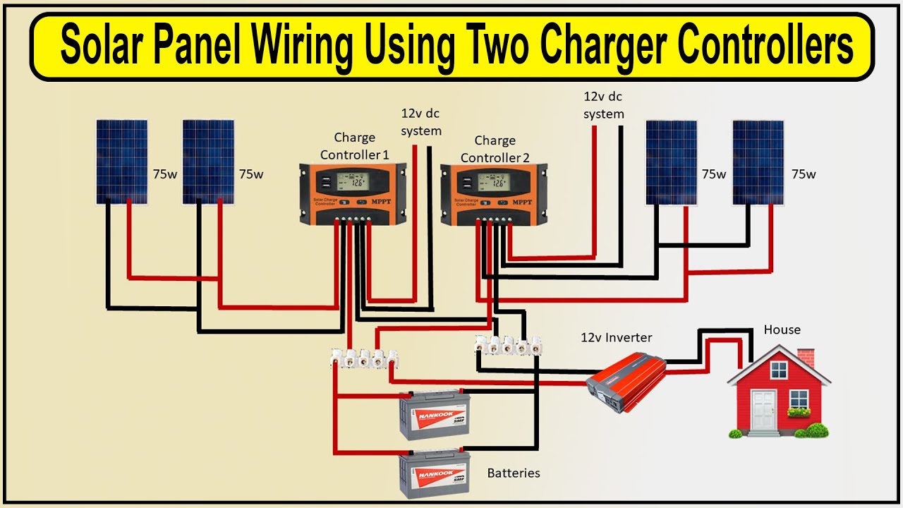
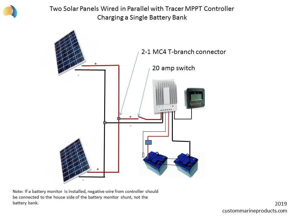
    1. Series and Parallel Configuration: Solar panels can be connected in series and parallel configurations to achieve the desired voltage and current. Ensure that the series and parallel configurations are balanced to optimize energy harvesting.
    2. Solar panel to MPPT controller wiring for remote locations

    3. MPPT Controller Configuration: Configure the MPPT controller to match the solar panel array’s voltage and current characteristics. Ensure that the MPPT controller is set to the correct input voltage and current limits.
    4. Wiring Harness: Use a wiring harness to connect the solar panel array to the MPPT controller. A wiring harness can simplify the wiring process and reduce the risk of errors.
    5. Fuses and Breakers: Install fuses and breakers to protect the system from overcurrent and short-circuit conditions. Ensure that the fuses and breakers are rated for the system’s voltage and current.
    6. Monitoring and Maintenance: Regularly monitor the system’s performance and perform maintenance tasks, such as cleaning the solar panels and checking the wiring system, to ensure optimal energy generation.

    Solar panel to MPPT controller wiring for remote locations

    Safety Considerations for Remote Locations

    Remote locations often pose unique safety challenges when it comes to solar panel wiring. The following safety considerations should be taken into account:

    1. Electrical Shock: Ensure that the wiring system is designed to prevent electrical shock. Use insulated wires and connectors, and ensure that the system is properly grounded.
    2. Fire Risk: The wiring system should be designed to minimize the risk of fire. Use flame-retardant materials and ensure that the system is properly ventilated.
    3. Lightning Protection: Remote locations are often prone to lightning strikes. Ensure that the system is equipped with lightning protection devices, such as surge protectors and grounding systems.
    4. Wildlife Protection: Remote locations may be inhabited by wildlife, such as birds and rodents. Ensure that the wiring system is designed to prevent wildlife damage and electrocution.

    Technical Requirements for Solar Panel to MPPT Controller Wiring

    The following technical requirements should be considered when wiring solar panels to MPPT controllers:

    1. Voltage and Current: Ensure that the wiring system is designed to handle the solar panel array’s voltage and current characteristics.
    2. Power Rating: Ensure that the wiring system is designed to handle the system’s power rating.
    3. Frequency and Harmonics: Ensure that the wiring system is designed to handle the system’s frequency and harmonics.
    4. Grounding and Bonding: Ensure that the wiring system is designed to provide a safe and efficient grounding and bonding system.
    5. Compliance with Standards: Ensure that the wiring system complies with relevant industry standards, such as UL 1703 and IEC 61215.

    Conclusion

    Wiring solar panels to MPPT controllers for remote locations requires careful consideration of technical, safety, and environmental factors. By following best practices, considering safety requirements, and meeting technical specifications, you can ensure efficient and safe energy generation from your solar panel system. Regular monitoring and maintenance are also crucial to ensure optimal system performance and extend the system’s lifespan. With the increasing demand for renewable energy sources, solar power is becoming an attractive option for remote locations. By understanding the requirements for solar panel to MPPT controller wiring, you can harness the power of the sun and contribute to a sustainable future.

    Recommendations for Future Work

    As the solar industry continues to evolve, there is a need for further research and development in the following areas:

    1. Improved MPPT Controller Efficiency: Developing more efficient MPPT controllers can optimize energy harvesting and reduce system costs.
    2. Advanced Wiring Materials: Developing advanced wiring materials that can withstand harsh environmental conditions can improve system reliability and durability.
    3. Remote Monitoring and Control: Developing remote monitoring and control systems can improve system performance, reduce maintenance costs, and enhance safety.
    4. Standardization of Wiring Practices: Standardizing wiring practices can simplify the installation process, reduce errors, and improve system safety.
    5. Education and Training: Providing education and training programs for solar panel installers and maintenance personnel can ensure that systems are installed and maintained correctly, reducing the risk of accidents and improving overall system performance.

    Solar panel to MPPT controller wiring for remote locations

  • Off-grid Solar Wiring Diagram For Battery Storage

    Off-grid Solar Wiring Diagram For Battery Storage

    “Off-grid solar wiring diagram for battery storage

    These systems allow homeowners and businesses to harness the power of the sun and store excess energy for later use, reducing reliance on the grid and lowering energy costs. However, designing and installing an off-grid solar system can be complex, requiring careful planning and attention to detail. In this article, we will provide a comprehensive guide to off-grid solar wiring diagrams for battery storage, covering the basics, system components, and best practices for installation.

    Off-grid solar wiring diagram for battery storage

    Introduction to Off-Grid Solar Systems

    Off-grid solar systems, also known as standalone or autonomous systems, are designed to operate independently of the grid. They consist of solar panels, a charge controller, a battery bank, and an inverter/charger. The solar panels generate electricity, which is then stored in the battery bank through the charge controller. The inverter/charger converts the DC power from the batteries to AC power, which is used to power appliances and loads.

    System Components

    To understand the wiring diagram, it’s essential to familiarize yourself with the system components:

    1. Solar Panels: Convert sunlight into DC electricity.
    2. Charge Controller: Regulates the flow of energy from the solar panels to the battery bank, preventing overcharging and damage.
    3. Battery Bank: Stores excess energy generated by the solar panels for later use.
    4. Inverter/Charger: Converts DC power from the battery bank to AC power, and also charges the batteries from an external source (e.g., a generator).
    5. Load Center: Distributes AC power to appliances and loads.
    6. Off-grid solar wiring diagram for battery storage

    7. Grounding System: Ensures the system is safely grounded to prevent electrical shock.

    Off-Grid Solar Wiring Diagram

    The wiring diagram for an off-grid solar system with battery storage is a critical component of the system design. The diagram illustrates the connections between the system components, including the solar panels, charge controller, battery bank, inverter/charger, and load center.

    Here is a basic wiring diagram for an off-grid solar system:

    Off-grid solar wiring diagram for battery storage

    1. Solar Panels:
      • Positive (+) terminal of each panel connected to the positive (+) terminal of the charge controller.
      • Negative (-) terminal of each panel connected to the negative (-) terminal of the charge controller.
      • Off-grid solar wiring diagram for battery storage

    2. Charge Controller:
      • Positive (+) terminal connected to the positive (+) terminal of the battery bank.
      • Negative (-) terminal connected to the negative (-) terminal of the battery bank.
    3. Battery Bank:
      • Positive (+) terminal connected to the positive (+) terminal of the inverter/charger.
      • Negative (-) terminal connected to the negative (-) terminal of the inverter/charger.
    4. Inverter/Charger:
      • Positive (+) terminal connected to the positive (+) terminal of the load center.
      • Negative (-) terminal connected to the negative (-) terminal of the load center.
    5. Load Center:
      • Connected to the inverter/charger, distributing AC power to appliances and loads.
    6. Grounding System:
      • Connected to the negative (-) terminal of the battery bank, inverter/charger, and load center.

    Best Practices for Installation

    To ensure a safe and efficient off-grid solar system, follow these best practices for installation:

    1. Use proper wiring and connectors: Use high-quality, UV-resistant wire and connectors to prevent damage from weather and sunlight.
    2. Follow manufacturer instructions: Adhere to the manufacturer’s instructions for each system component, including the charge controller, inverter/charger, and battery bank.
    3. Size the system correctly: Ensure the system is sized to meet the energy needs of the loads, taking into account the solar panel array, battery bank, and inverter/charger.
    4. Monitor the system: Install a monitoring system to track the performance of the solar panels, battery bank, and inverter/charger.
    5. Perform regular maintenance: Regularly inspect the system, clean the solar panels, and check the battery bank and inverter/charger for signs of wear or damage.

    Safety Considerations

    Off-grid solar systems can be hazardous if not installed and maintained properly. To ensure safety:

    1. Hire a qualified installer: Engage a licensed and experienced solar installer to design and install the system.
    2. Follow electrical codes: Adhere to local electrical codes and regulations, including the National Electric Code (NEC).
    3. Use protective equipment: Use personal protective equipment (PPE), such as gloves and safety glasses, when working with electrical systems.
    4. Ground the system: Ensure the system is properly grounded to prevent electrical shock.
    5. Install a disconnect: Install a disconnect switch or circuit breaker to isolate the system for maintenance and repair.

    Conclusion

    Off-grid solar systems with battery storage offer a reliable and sustainable solution for energy independence. A well-designed wiring diagram is essential to ensure a safe and efficient system. By following best practices for installation, monitoring, and maintenance, you can enjoy the benefits of off-grid solar energy while minimizing the risks. Remember to consult with a qualified solar installer and adhere to local electrical codes and regulations to ensure a safe and successful installation.

    Additional Resources

    For further information on off-grid solar systems and wiring diagrams, refer to the following resources:

    1. National Electric Code (NEC): A comprehensive guide to electrical codes and regulations.
    2. International Association of Electrical Inspectors (IAEI): A resource for electrical inspectors and professionals.
    3. Solar Energy Industries Association (SEIA): A trade association providing guidance on solar energy systems and installation.
    4. National Renewable Energy Laboratory (NREL): A research organization providing technical assistance and resources on renewable energy systems.

    By following the guidelines and best practices outlined in this article, you can create a safe and efficient off-grid solar system with battery storage, harnessing the power of the sun to reduce your energy costs and reliance on the grid.

    Off-grid solar wiring diagram for battery storage

  • Solar Panel Wiring Setup With MPPT Charge Controller For Efficiency

    Solar Panel Wiring Setup With MPPT Charge Controller For Efficiency

    “Solar panel wiring setup with MPPT charge controller for efficiency

    The system voltage will depend on the voltage of the solar panels, battery bank, and inverter.

  • Solar panel wiring setup with MPPT charge controller for efficiency

  • Choose the Correct Wire Size: Choose the correct wire size based on the system voltage and current. A larger wire size will reduce energy losses and ensure safe operation.
  • Configure the Solar Panel Array: Configure the solar panel array to match the system voltage. For example, if the system voltage is 24V, you can connect two 12V solar panels in series to achieve the desired voltage.
  • Install the MPPT Charge Controller: Install the MPPT charge controller between the solar panel array and the battery bank. Ensure that the charge controller is rated for the maximum power output of the solar panel array.
  • Connect the Battery Bank: Connect the battery bank to the MPPT charge controller. Ensure that the battery bank is rated for the maximum power output of the solar panel array.
  • Add Overcurrent Protection: Add overcurrent protection devices, such as fuses or circuit breakers, to protect the system from overcurrent conditions.
  • Monitor the System: Monitor the system performance using a monitoring system, such as a remote monitoring system or a local display.
  • Best Practices for Solar Panel Wiring Setup

    To ensure a safe and efficient solar panel wiring setup, follow these best practices:

      Solar panel wiring setup with MPPT charge controller for efficiency

    1. Use High-Quality Wires and Connectors: Use high-quality wires and connectors that are rated for the system voltage and current.
    2. Keep Wires Organized: Keep wires organized and secured to prevent damage and reduce energy losses.
    3. Avoid Overloading: Avoid overloading the system by ensuring that the wire size and overcurrent protection devices are rated for the maximum power output of the solar panel array.
    4. Use Weatherproof Enclosures: Use weatherproof enclosures to protect the wiring setup from environmental factors, such as rain and extreme temperatures.
    5. Regularly Inspect the System: Regularly inspect the system to ensure that it is operating safely and efficiently.
    6. Solar panel wiring setup with MPPT charge controller for efficiency

    Common Mistakes to Avoid

    When designing a solar panel wiring setup with an MPPT charge controller, avoid the following common mistakes:

    1. Incorrect Wire Size: Using an incorrect wire size can lead to energy losses and reduced system performance.
    2. Solar panel wiring setup with MPPT charge controller for efficiency

    3. Inadequate Overcurrent Protection: Inadequate overcurrent protection can lead to safety hazards and system damage.
    4. Poorly Configured Solar Panel Array: A poorly configured solar panel array can lead to reduced energy production and system performance.
    5. Insufficient Monitoring: Insufficient monitoring can make it difficult to identify system issues and optimize system performance.

    Conclusion

    A well-designed solar panel wiring setup with an MPPT charge controller is essential for maximizing the efficiency and energy production of a solar power system. By following the steps outlined in this article and avoiding common mistakes, you can create a safe and efficient solar panel wiring setup that meets your energy needs. Remember to regularly inspect and monitor the system to ensure that it is operating at optimal levels. With the right design and maintenance, a solar power system can provide reliable and clean energy for years to come.

    Additional Tips and Recommendations

    • Always follow the manufacturer’s instructions for the MPPT charge controller and other system components.
    • Consider using a solar panel wiring diagram to help design and visualize the wiring setup.
    • Use a wire sizing calculator to determine the correct wire size for the system.
    • Consider adding a grounding system to protect the system from lightning strikes and other electrical surges.
    • Regularly clean and maintain the solar panels to ensure maximum energy production.

    By following these tips and recommendations, you can create a solar panel wiring setup that is safe, efficient, and reliable. Whether you are a homeowner, business owner, or solar installer, a well-designed solar panel wiring setup with an MPPT charge controller is essential for maximizing the benefits of solar power.

    Solar panel wiring setup with MPPT charge controller for efficiency

  • Solar Battery Bank Wiring Diagram For Home

    Solar Battery Bank Wiring Diagram For Home

    “Solar battery bank wiring diagram for home

    One of the key components of a solar power system is the battery bank, which stores excess energy generated by the solar panels during the day for use at night or during periods of low sunlight. In this article, we will delve into the world of solar battery bank wiring diagrams for homes, providing a comprehensive guide on how to design and install a safe and efficient system.

    Solar battery bank wiring diagram for home

    Introduction to Solar Battery Banks

    A solar battery bank is a collection of deep cycle batteries connected together to store excess energy generated by a solar panel array. The battery bank is designed to provide a stable and reliable source of power to the home, even when the sun is not shining. The size and configuration of the battery bank depend on the energy needs of the home, the size of the solar panel array, and the desired level of autonomy.

    Components of a Solar Battery Bank

    A typical solar battery bank consists of the following components:

    1. Deep Cycle Batteries: These are the heart of the battery bank, designed to withstand deep discharging and recharging cycles.
    2. Battery Management System (BMS): This system monitors and controls the battery bank, preventing overcharging or over-discharging, and ensuring safe operation.
    3. Charge Controller: This device regulates the flow of energy from the solar panels to the battery bank, preventing overcharging and ensuring efficient charging.
    4. Inverter/Charger: This device converts DC power from the battery bank to AC power for use in the home, and also charges the battery bank from the grid or a generator.
    5. Wiring and Connectors: These connect the various components of the battery bank together, ensuring safe and efficient energy transfer.
    6. Solar battery bank wiring diagram for home

    Solar Battery Bank Wiring Diagram

    A solar battery bank wiring diagram is a detailed illustration of the electrical connections between the various components of the system. The diagram shows the configuration of the batteries, the charge controller, the inverter/charger, and the wiring and connectors. A well-designed wiring diagram is essential to ensure safe and efficient operation of the system.

    Types of Solar Battery Bank Configurations

    There are several types of solar battery bank configurations, including:

    Solar battery bank wiring diagram for home

    1. Series Configuration: In this configuration, batteries are connected in series, with the positive terminal of one battery connected to the negative terminal of the next battery. This configuration increases the voltage of the battery bank, but reduces the ampere-hour (Ah) capacity.
    2. Parallel Configuration: In this configuration, batteries are connected in parallel, with all positive terminals connected together and all negative terminals connected together. This configuration increases the Ah capacity of the battery bank, but does not increase the voltage.
    3. Series-Parallel Configuration: In this configuration, batteries are connected in a combination of series and parallel, with multiple series strings connected in parallel. This configuration provides a balance between voltage and Ah capacity.

    Solar battery bank wiring diagram for home

    Designing a Solar Battery Bank Wiring Diagram

    Designing a solar battery bank wiring diagram requires careful consideration of several factors, including:

    1. Battery Size and Type: The size and type of batteries will determine the configuration of the battery bank and the wiring diagram.
    2. Charge Controller Capacity: The charge controller must be sized to handle the maximum charging current from the solar panels.
    3. Inverter/Charger Capacity: The inverter/charger must be sized to handle the maximum load of the home.
    4. Wiring and Connector Size: The wiring and connectors must be sized to handle the maximum current flowing through the system.
    5. Safety Features: The wiring diagram must include safety features such as fuses, circuit breakers, and grounding systems to protect against electrical shock and fire.

    Example of a Solar Battery Bank Wiring Diagram

    Here is an example of a solar battery bank wiring diagram for a small home:

    • Battery Bank: 4 x 12V, 200Ah deep cycle batteries connected in series-parallel configuration (2 series strings of 2 batteries each)
    • Charge Controller: 40A MPPT charge controller
    • Inverter/Charger: 2000W, 24V inverter/charger
    • Wiring and Connectors: 10AWG copper wire, with lugs and connectors rated for 40A

    The wiring diagram would show the following connections:

    • Battery Bank: The positive terminal of each battery is connected to the negative terminal of the next battery in series, with the positive terminal of the first battery connected to the charge controller.
    • Charge Controller: The charge controller is connected to the positive terminal of the battery bank and to the solar panel array.
    • Inverter/Charger: The inverter/charger is connected to the positive terminal of the battery bank and to the load center of the home.
    • Wiring and Connectors: The wiring and connectors are sized to handle the maximum current flowing through the system, with fuses and circuit breakers installed to protect against electrical shock and fire.

    Conclusion

    Designing a solar battery bank wiring diagram for a home requires careful consideration of several factors, including battery size and type, charge controller capacity, inverter/charger capacity, wiring and connector size, and safety features. By following the guidelines outlined in this article, homeowners can create a safe and efficient solar battery bank wiring diagram that meets their energy needs and provides a reliable source of power for years to come.

    Recommendations

    1. Hire a Professional: If you are not experienced in designing and installing solar battery bank wiring diagrams, it is highly recommended to hire a professional to ensure safe and efficient operation of the system.
    2. Use High-Quality Components: Use high-quality components, including batteries, charge controllers, inverters/chargers, and wiring and connectors, to ensure reliable operation and long lifespan of the system.
    3. Follow Safety Guidelines: Follow safety guidelines and regulations, including the National Electric Code (NEC), to ensure safe installation and operation of the system.
    4. Monitor and Maintain the System: Regularly monitor and maintain the system to ensure optimal performance and extend the lifespan of the components.

    By following these recommendations and guidelines, homeowners can enjoy a safe and efficient solar battery bank wiring diagram that provides a reliable source of power for their home.

    Solar battery bank wiring diagram for home

  • MPPT Charge Controller Wiring For Large Solar Panel Arrays

    “MPPT charge controller wiring for large solar panel arrays

    Large solar panel arrays are being installed to generate clean energy, reduce carbon footprint, and minimize reliance on the grid. However, to ensure the efficient and safe operation of these arrays, it’s crucial to understand the importance of proper wiring, particularly when it comes to Maximum Power Point Tracking (MPPT) charge controllers.

    MPPT charge controller wiring for large solar panel arrays

    In this article, we’ll delve into the world of MPPT charge controller wiring for large solar panel arrays, covering the basics, best practices, and troubleshooting tips. Whether you’re a seasoned solar installer or a DIY enthusiast, this comprehensive guide will help you navigate the complexities of MPPT charge controller wiring and ensure your solar panel array operates at maximum efficiency.

    What is an MPPT Charge Controller?

    An MPPT charge controller is a critical component in a solar panel array, responsible for regulating the flow of energy from the solar panels to the battery bank or grid. MPPT stands for Maximum Power Point Tracking, which refers to the controller’s ability to track the maximum power point of the solar panels and adjust the energy flow accordingly. This ensures that the solar panels operate at their maximum efficiency, even in changing environmental conditions.

    MPPT charge controllers are designed to optimize energy harvesting, reduce energy losses, and prevent overcharging or undercharging of the battery bank. They’re particularly useful in large solar panel arrays, where multiple solar panels are connected in series and parallel to generate high voltages and currents.

    MPPT Charge Controller Wiring Basics

    When it comes to wiring an MPPT charge controller for a large solar panel array, there are several key considerations to keep in mind:

    1. Solar Panel Configuration: The solar panels should be configured in a way that allows the MPPT charge controller to operate efficiently. This typically involves connecting multiple solar panels in series to create a higher voltage string, and then connecting multiple strings in parallel to increase the overall current.
    2. Voltage and Current Ratings: The MPPT charge controller should be rated to handle the maximum voltage and current output of the solar panel array. Ensure that the controller’s voltage and current ratings match or exceed the array’s specifications.
    3. Wire Sizing and Length: The wire size and length between the solar panels, MPPT charge controller, and battery bank or grid connection should be carefully selected to minimize energy losses. Use a wire sizing chart to determine the correct wire gauge for your application.
    4. MPPT charge controller wiring for large solar panel arrays

    5. Connectors and Terminals: Use high-quality connectors and terminals to ensure secure and reliable connections between the solar panels, MPPT charge controller, and other components.

    Wiring Configurations for Large Solar Panel Arrays

    There are several wiring configurations that can be used for large solar panel arrays, depending on the specific application and requirements:

      MPPT charge controller wiring for large solar panel arrays

    1. Series-Parallel Configuration: This is the most common configuration for large solar panel arrays. Multiple solar panels are connected in series to create a higher voltage string, and then multiple strings are connected in parallel to increase the overall current.
    2. Parallel Configuration: In this configuration, multiple solar panels are connected in parallel to increase the overall current. This configuration is often used for smaller solar panel arrays or when the solar panels have a lower voltage rating.
    3. Series Configuration: In this configuration, multiple solar panels are connected in series to create a higher voltage string. This configuration is often used for larger solar panel arrays or when the solar panels have a higher voltage rating.

    Best Practices for MPPT Charge Controller Wiring

    MPPT charge controller wiring for large solar panel arrays

    To ensure safe and efficient operation of your large solar panel array, follow these best practices for MPPT charge controller wiring:

    1. Use High-Quality Wire and Connectors: Use high-quality wire and connectors to minimize energy losses and ensure reliable connections.
    2. Keep Wire Lengths Short: Keep wire lengths as short as possible to reduce energy losses and minimize the risk of electrical shock.
    3. Use Protective Devices: Use protective devices such as fuses, circuit breakers, and surge protectors to protect the MPPT charge controller and other components from overcurrent and surge conditions.
    4. Grounding and Bonding: Ensure proper grounding and bonding of the solar panel array, MPPT charge controller, and other components to prevent electrical shock and ensure safe operation.
    5. Regular Maintenance: Regularly inspect and maintain the wiring and connections to ensure they remain secure and reliable.

    Troubleshooting MPPT Charge Controller Wiring Issues

    If you encounter issues with your MPPT charge controller wiring, follow these troubleshooting steps:

    1. Check Wire Connections: Check the wire connections between the solar panels, MPPT charge controller, and other components to ensure they are secure and reliable.
    2. Verify Voltage and Current Ratings: Verify that the MPPT charge controller’s voltage and current ratings match or exceed the solar panel array’s specifications.
    3. Check for Short Circuits: Check for short circuits between the solar panels, MPPT charge controller, and other components.
    4. Check for Open Circuits: Check for open circuits between the solar panels, MPPT charge controller, and other components.
    5. Consult the Manufacturer’s Manual: Consult the manufacturer’s manual for the MPPT charge controller and other components to ensure you’re following the correct wiring and configuration procedures.

    Conclusion

    MPPT charge controller wiring for large solar panel arrays requires careful planning, attention to detail, and a thorough understanding of the underlying principles. By following the best practices and guidelines outlined in this article, you can ensure safe and efficient operation of your solar panel array and maximize energy harvesting. Remember to always consult the manufacturer’s manual and seek professional assistance if you’re unsure about any aspect of the wiring or configuration process. With proper MPPT charge controller wiring, you can enjoy the benefits of renewable energy and contribute to a sustainable future.

    Additional Resources

    For further information on MPPT charge controller wiring and large solar panel arrays, refer to the following resources:

    • National Electric Code (NEC) guidelines for solar panel installations
    • Manufacturer’s manuals for MPPT charge controllers and other components
    • Online forums and discussion groups for solar panel installers and enthusiasts
    • Industry publications and research papers on solar panel technology and best practices

    By staying informed and up-to-date on the latest developments and best practices in MPPT charge controller wiring, you can ensure your large solar panel array operates safely and efficiently, providing clean energy for years to come.

    MPPT charge controller wiring for large solar panel arrays

  • Wiring Diagram For Off-grid Solar Power System Installation

    Wiring Diagram For Off-grid Solar Power System Installation

    “Wiring diagram for off-grid solar power system installation

    These systems provide a reliable and sustainable source of energy, independent of the utility grid. However, installing an off-grid solar power system requires careful planning and attention to detail, particularly when it comes to wiring. In this article, we will provide a comprehensive guide to creating a wiring diagram for an off-grid solar power system installation, including the essential components, wiring requirements, and safety considerations.

    Wiring diagram for off-grid solar power system installation

    Introduction to Off-Grid Solar Power Systems

    An off-grid solar power system is designed to generate electricity from solar panels and store it in batteries for later use. The system typically consists of solar panels, a charge controller, a battery bank, an inverter/charger, and a load center. The solar panels convert sunlight into direct current (DC) electricity, which is then sent to the charge controller to regulate the voltage and prevent overcharging of the batteries. The batteries store excess energy generated by the solar panels during the day for use at night or during periods of low sunlight. The inverter/charger converts the DC power from the batteries into alternating current (AC) electricity, which can be used to power appliances and loads.

    Essential Components of an Off-Grid Solar Power System

    Before creating a wiring diagram, it is essential to understand the components of an off-grid solar power system and their functions:

    1. Solar Panels: Convert sunlight into DC electricity.
    2. Charge Controller: Regulates the voltage and prevents overcharging of the batteries.
    3. Battery Bank: Stores excess energy generated by the solar panels.
    4. Inverter/Charger: Converts DC power from the batteries into AC electricity.
    5. Load Center: Distributes AC power to appliances and loads.
    6. Wiring diagram for off-grid solar power system installation

    7. Transfer Switch: Automatically switches between the solar power system and a backup generator (if installed).
    8. Grounding System: Provides a safe path to ground for fault currents and lightning strikes.

    Wiring Requirements for an Off-Grid Solar Power System

    The wiring requirements for an off-grid solar power system are critical to ensure safe and efficient operation. The following are some key considerations:

    Wiring diagram for off-grid solar power system installation

    1. Wire Size and Type: The wire size and type should be suitable for the ampacity and voltage of the system. Typically, 10 AWG or 12 AWG wire is used for the DC cables, and 14 AWG or 16 AWG wire is used for the AC cables.
    2. Insulation and Protection: The wires should be insulated and protected from damage, moisture, and extreme temperatures. UV-resistant cable ties and conduit can be used to secure the wires.
    3. Color Coding: The wires should be color-coded to identify the positive and negative DC cables, as well as the AC cables.
    4. Grounding and Bonding: The system should be grounded and bonded to ensure electrical safety and prevent shock hazards.
    5. Wiring diagram for off-grid solar power system installation

    Creating a Wiring Diagram for an Off-Grid Solar Power System

    A wiring diagram is a visual representation of the electrical connections between the components of an off-grid solar power system. The diagram should include the following:

    1. Component Symbols: The diagram should use standard symbols to represent each component, such as solar panels, charge controllers, batteries, inverters, and load centers.
    2. Wire Connections: The diagram should show the wire connections between each component, including the wire size, type, and color coding.
    3. Grounding and Bonding: The diagram should show the grounding and bonding connections, including the grounding rod, busbars, and equipment grounding conductors.
    4. Fuses and Circuit Breakers: The diagram should show the fuses and circuit breakers used to protect the system from overcurrent and fault conditions.

    Example Wiring Diagram for an Off-Grid Solar Power System

    The following is an example wiring diagram for a basic off-grid solar power system:

    [Insert diagram]

    The diagram shows the solar panels connected to the charge controller, which is connected to the battery bank. The battery bank is connected to the inverter/charger, which is connected to the load center. The load center distributes AC power to the appliances and loads. The system is grounded and bonded to ensure electrical safety.

    Safety Considerations for Off-Grid Solar Power System Installation

    The installation of an off-grid solar power system requires careful attention to safety considerations, including:

    1. Electrical Shock: The system should be designed and installed to prevent electrical shock hazards, including proper grounding and bonding.
    2. Fire Hazard: The system should be designed and installed to prevent fire hazards, including proper ventilation and heat management.
    3. Lightning Protection: The system should be designed and installed to protect against lightning strikes, including the use of surge protectors and lightning arresters.
    4. Overcurrent Protection: The system should be designed and installed to protect against overcurrent conditions, including the use of fuses and circuit breakers.

    Conclusion

    Creating a wiring diagram for an off-grid solar power system installation is a critical step in ensuring safe and efficient operation. The diagram should include the essential components, wiring requirements, and safety considerations. By following the guidelines outlined in this article, installers and system designers can create a comprehensive wiring diagram that meets the needs of the system and ensures reliable operation. Remember to always follow local electrical codes and regulations, and consult with a licensed electrician if you are unsure about any aspect of the installation.

    Recommendations for Future Work

    As the use of off-grid solar power systems continues to grow, there is a need for further research and development in the following areas:

    1. Standardization of Wiring Diagrams: The development of standardized wiring diagrams for off-grid solar power systems would improve consistency and clarity.
    2. Advances in Component Technology: The development of new component technologies, such as more efficient solar panels and batteries, would improve the performance and reliability of off-grid solar power systems.
    3. Improved Safety Features: The development of improved safety features, such as advanced surge protection and lightning arresters, would enhance the safety and reliability of off-grid solar power systems.

    By addressing these areas, we can continue to improve the performance, safety, and reliability of off-grid solar power systems, and promote the widespread adoption of renewable energy sources.

    Wiring diagram for off-grid solar power system installation

  • MPPT Charge Controller: This device optimizes energy harvest from the solar panels and regulates the flow of energy to the battery bank.
  • Battery Bank: A collection of deep cycle batteries that store excess energy generated by the solar panels for later use.
  • Inverter/Charger: This device converts DC power from the battery bank to AC (alternating current) power, which is usable by household appliances.
  • MPPT Charge Controller

    An MPPT charge controller is a critical component of any off-grid solar power system. Its primary function is to optimize energy harvest from the solar panels by tracking the maximum power point (MPP) of the solar array. This ensures that the system generates the maximum amount of energy possible, even in varying environmental conditions.

    Wiring Diagram

    The wiring diagram for a solar panel to MPPT charge controller system is relatively straightforward. Here’s a step-by-step guide:

    Components Needed

    Wiring Diagram Steps

    1. Connect the Solar Panels: Connect the solar panels in series or parallel, depending on the system design. Use MC4 connectors to connect the panels to each other and to the MPPT charge controller.
    2. Connect the MPPT Charge Controller: Connect the positive (+) wire from the solar panel array to the positive input terminal on the MPPT charge controller. Connect the negative (-) wire from the solar panel array to the negative input terminal on the MPPT charge controller.
    3. Connect the Battery Bank: Connect the positive (+) wire from the battery bank to the positive output terminal on the MPPT charge controller. Connect the negative (-) wire from the battery bank to the negative output terminal on the MPPT charge controller.
    4. Connect the Inverter/Charger (Optional): If you’re using an inverter/charger, connect the positive (+) wire from the battery bank to the positive input terminal on the inverter/charger. Connect the negative (-) wire from the battery bank to the negative input terminal on the inverter/charger.

    Example Wiring Diagram

    Here’s an example wiring diagram for a basic off-grid solar power system:

    Solar Panel Array (3 panels in series)
    Positive (+) wire → MPPT Charge Controller (Positive Input Terminal)
    Negative (-) wire → MPPT Charge Controller (Negative Input Terminal)

    MPPT Charge Controller
    Positive (+) wire → Battery Bank (Positive Terminal)
    Negative (-) wire → Battery Bank (Negative Terminal)

    Battery Bank
    Positive (+) wire → Inverter/Charger (Positive Input Terminal)
    Negative (-) wire → Inverter/Charger (Negative Input Terminal)

    Tips and Considerations

    When wiring your solar panel to MPPT charge controller system, keep the following tips and considerations in mind:

    Safety Precautions

    When working with electrical systems, safety should always be the top priority. Here are some safety precautions to keep in mind:

    Conclusion

    In conclusion, the wiring diagram for a solar panel to MPPT charge controller system is a critical component of any off-grid solar power system. By following the steps outlined in this article, you can ensure that your system is properly wired and functioning efficiently. Remember to always follow safety precautions when working with electrical systems, and don’t hesitate to seek professional help if you’re unsure about any aspect of the installation process.

    Additional Resources

    For further information on solar panel to MPPT charge controller wiring diagrams, we recommend consulting the following resources:

    By following the guidelines outlined in this article and consulting additional resources, you’ll be well on your way to creating a safe, efficient, and reliable off-grid solar power system.

  • How To Wire Solar Panels To MPPT Controller

    How To Wire Solar Panels To MPPT Controller

    “How to wire solar panels to MPPT controller

    One of the key components of a solar power system is the Maximum Power Point Tracking (MPPT) controller, which plays a crucial role in optimizing energy production. In this article, we will provide a step-by-step guide on how to wire solar panels to an MPPT controller, ensuring that you can harness the full potential of your solar power system.

    How to wire solar panels to MPPT controller

    Introduction to MPPT Controllers

    Before we dive into the wiring process, let’s take a brief look at what an MPPT controller is and how it works. An MPPT controller is an electronic device that tracks the maximum power point of a solar panel array and adjusts the output voltage to match the battery bank’s voltage. This ensures that the maximum amount of energy is extracted from the solar panels and stored in the battery bank.

    MPPT controllers offer several benefits, including:

    • Increased energy production: By tracking the maximum power point, MPPT controllers can increase energy production by up to 30% compared to traditional charge controllers.
    • Improved battery life: MPPT controllers help to prevent overcharging and undercharging of the battery bank, which can extend its lifespan.
    • Flexibility: MPPT controllers can be used with a wide range of solar panel and battery configurations.

    Preparation and Planning

    Before starting the wiring process, it’s essential to plan and prepare your solar power system. Here are some steps to follow:

    How to wire solar panels to MPPT controller

    1. Determine your system requirements: Calculate the total wattage of your solar panel array and the voltage of your battery bank.
    2. Choose the right MPPT controller: Select an MPPT controller that matches your system requirements and is compatible with your solar panel and battery configurations.
    3. Gather necessary materials: Ensure you have all the necessary materials, including solar panels, an MPPT controller, batteries, wiring, and connectors.
    4. Check local regulations and codes: Familiarize yourself with local electrical codes and regulations to ensure compliance.
    5. How to wire solar panels to MPPT controller

    Wiring Solar Panels to an MPPT Controller

    Now that we’ve covered the basics, let’s move on to the wiring process. Here’s a step-by-step guide:

    Step 1: Connect Solar Panels in Series or Parallel

    The first step is to connect your solar panels in either series or parallel configurations. The configuration you choose will depend on your system requirements and the specifications of your solar panels.

    How to wire solar panels to MPPT controller

    • Series configuration: Connect the positive terminal of one solar panel to the negative terminal of the next solar panel. This will increase the voltage of the array.
    • Parallel configuration: Connect the positive terminals of multiple solar panels together and the negative terminals together. This will increase the current of the array.

    Step 2: Connect the Solar Panel Array to the MPPT Controller

    Once you’ve connected your solar panels, it’s time to connect the array to the MPPT controller.

    1. Identify the input terminals: Locate the input terminals on the MPPT controller, usually marked as "Solar Panel + " and "Solar Panel -".
    2. Connect the solar panel array: Connect the positive terminal of the solar panel array to the "Solar Panel + " terminal and the negative terminal to the "Solar Panel – " terminal.

    Step 3: Connect the Battery Bank to the MPPT Controller

    Next, connect the battery bank to the MPPT controller.

    1. Identify the output terminals: Locate the output terminals on the MPPT controller, usually marked as "Battery + " and "Battery -".
    2. Connect the battery bank: Connect the positive terminal of the battery bank to the "Battery + " terminal and the negative terminal to the "Battery – " terminal.

    Step 4: Configure the MPPT Controller

    Most MPPT controllers come with a display screen and buttons that allow you to configure the device. Here are some common settings to configure:

    1. Battery type: Select the type of battery you’re using (e.g., lead-acid, lithium-ion).
    2. Battery voltage: Set the battery voltage to match your battery bank’s voltage.
    3. Charge current: Set the charge current to match your system requirements.
    4. Maximum power point tracking: Enable MPPT tracking to optimize energy production.

    Step 5: Test and Verify the System

    Once you’ve completed the wiring process and configured the MPPT controller, it’s time to test and verify the system.

    1. Check the display screen: Verify that the MPPT controller is displaying the correct information, such as voltage, current, and power output.
    2. Check the battery bank: Verify that the battery bank is charging correctly and that the voltage is within the expected range.
    3. Check the solar panel array: Verify that the solar panel array is producing power and that the voltage and current are within the expected range.

    Troubleshooting Common Issues

    If you encounter any issues during the wiring process or after the system is up and running, here are some common problems to look out for:

    1. No power output: Check that the solar panel array is connected correctly and that the MPPT controller is configured correctly.
    2. Low power output: Check that the solar panel array is clean and free of shade, and that the MPPT controller is configured correctly.
    3. Overcharging or undercharging: Check that the battery bank is connected correctly and that the MPPT controller is configured correctly.

    Conclusion

    Wiring solar panels to an MPPT controller is a straightforward process that requires some planning and attention to detail. By following the steps outlined in this article, you can ensure that your solar power system is configured correctly and operating at maximum efficiency. Remember to always follow local regulations and codes, and to consult the manufacturer’s instructions for specific guidance on your MPPT controller and solar panel array.

    Additional Tips and Recommendations

    1. Use high-quality wiring and connectors: Ensure that you use high-quality wiring and connectors to minimize losses and ensure reliable connections.
    2. Monitor your system performance: Regularly monitor your system’s performance to identify any issues or areas for improvement.
    3. Perform regular maintenance: Regularly inspect and maintain your solar power system to ensure optimal performance and longevity.

    By following these tips and recommendations, you can enjoy a reliable and efficient solar power system that meets your energy needs for years to come.

    How to wire solar panels to MPPT controller

  • Step‑by‑step EV Component Diagram Tutorial

    Step‑by‑step EV Component Diagram Tutorial

    An EV component diagram is a visual representation of the various parts that work together to power an electric vehicle. In this tutorial, we will walk you through a step-by-step guide on creating an EV component diagram, highlighting the key components and their relationships.

    step‑by‑step EV component diagram tutorial

    Introduction to EV Components

    Before we dive into the tutorial, let’s take a brief look at the key components that make up an electric vehicle:

    1. Battery Pack: The battery pack is the energy storage system of the EV, providing power to the electric motor.
    2. Electric Motor: The electric motor is responsible for propelling the vehicle, using the energy stored in the battery pack.
    3. Power Electronics: The power electronics system controls the flow of energy between the battery pack and the electric motor.
    4. Transmission: The transmission system transmits the power from the electric motor to the wheels.
    5. Charging System: The charging system allows the vehicle to be charged from an external power source.
    6. Thermal Management System: The thermal management system regulates the temperature of the vehicle’s components, ensuring optimal performance and longevity.

    step‑by‑step EV component diagram tutorial

    Step 1: Gather Information and Resources

    To create an accurate EV component diagram, you will need to gather information about the specific vehicle you are working with. This can include:

    • Technical specifications and documentation
    • Component diagrams and schematics
    • step‑by‑step EV component diagram tutorial

    • Manufacturer information and resources
    • Online forums and communities

    Step 2: Choose a Diagramming Tool

    There are many diagramming tools available, both online and offline, that can be used to create an EV component diagram. Some popular options include:

    step‑by‑step EV component diagram tutorial

    • Microsoft Visio
    • Autodesk AutoCAD
    • Lucidchart
    • Draw.io

    Step 3: Start with the Battery Pack

    The battery pack is the heart of the EV, and it’s a good place to start your diagram. Begin by adding a rectangle or box to represent the battery pack, and label it accordingly.

    • Battery Pack Components: Include the following components within the battery pack:
      • Battery cells
      • Battery management system (BMS)
      • Electrical connections

    Step 4: Add the Electric Motor

    The electric motor is the next key component to add to your diagram. Draw a separate rectangle or box to represent the electric motor, and label it accordingly.

    • Electric Motor Components: Include the following components within the electric motor:
      • Motor windings
      • Rotor and stator
      • Electrical connections

    Step 5: Add the Power Electronics

    The power electronics system controls the flow of energy between the battery pack and the electric motor. Add a separate rectangle or box to represent the power electronics, and label it accordingly.

    • Power Electronics Components: Include the following components within the power electronics:
      • Inverter
      • Converter
      • Electrical connections

    Step 6: Add the Transmission

    The transmission system transmits the power from the electric motor to the wheels. Add a separate rectangle or box to represent the transmission, and label it accordingly.

    • Transmission Components: Include the following components within the transmission:
      • Gearbox
      • Differential
      • Electrical connections

    Step 7: Add the Charging System

    The charging system allows the vehicle to be charged from an external power source. Add a separate rectangle or box to represent the charging system, and label it accordingly.

    • Charging System Components: Include the following components within the charging system:
      • Charging port
      • Charging cable
      • Electrical connections

    Step 8: Add the Thermal Management System

    The thermal management system regulates the temperature of the vehicle’s components, ensuring optimal performance and longevity. Add a separate rectangle or box to represent the thermal management system, and label it accordingly.

    • Thermal Management System Components: Include the following components within the thermal management system:
      • Cooling system
      • Heating system
      • Electrical connections

    Step 9: Connect the Components

    Now that you have added all the key components, it’s time to connect them. Use lines and arrows to show the relationships between the components, including:

    • Electrical connections
    • Mechanical connections
    • Fluid connections (if applicable)

    Step 10: Review and Refine

    Review your diagram to ensure that all components are included and accurately represented. Refine your diagram as needed, making any necessary adjustments or additions.

    Example EV Component Diagram

    Here is an example of a basic EV component diagram, showing the key components and their relationships:

                                          +---------------+
                                          |  Battery Pack  |
                                          +---------------+
                                                 |
                                                 |
                                                 v
                                          +---------------+
                                          |  Power Electronics  |
                                          +---------------+
                                                 |
                                                 |
                                                 v
                                          +---------------+
                                          |  Electric Motor  |
                                          +---------------+
                                                 |
                                                 |
                                                 v
                                          +---------------+
                                          |  Transmission  |
                                          +---------------+
                                                 |
                                                 |
                                                 v
                                          +---------------+
                                          |  Wheels  |
                                          +---------------+
                                                 |
                                                 |
                                                 v
                                          +---------------+
                                          |  Charging System  |
                                          +---------------+
                                                 |
                                                 |
                                                 v
                                          +---------------+
                                          |  Thermal Management  |
                                          +---------------+

    Conclusion

    Creating an EV component diagram is a valuable exercise for anyone looking to understand the inner workings of an electric vehicle. By following the steps outlined in this tutorial, you can create a comprehensive and accurate diagram of the key components and their relationships. Whether you are an engineer, a technician, or simply an EV enthusiast, this tutorial provides a solid foundation for exploring the world of electric vehicles.

    Future Developments

    As the EV industry continues to evolve, new technologies and components are being developed to improve performance, range, and efficiency. Some potential areas of future development include:

    • Advanced Battery Technologies: New battery chemistries and designs, such as solid-state batteries and lithium-air batteries, are being developed to improve energy density and reduce costs.
    • More Efficient Electric Motors: Researchers are working on new motor designs, such as permanent magnet motors and switched reluctance motors, to improve efficiency and reduce weight.
    • Improved Power Electronics: Advances in power electronics, such as silicon carbide (SiC) and gallium nitride (GaN) devices, are enabling faster switching times and higher power densities.

    As these new technologies are developed and integrated into EVs, the component diagram will continue to evolve, reflecting the changing landscape of the industry.

    References

    • National Renewable Energy Laboratory (NREL): "Electric Vehicle Basics"
    • International Council on Clean Transportation (ICCT): "Electric Vehicle Components"
    • Society of Automotive Engineers (SAE): "Electric Vehicle Architecture"
    • Electric Vehicle Association (EVA): "EV Component Diagrams"

    step‑by‑step EV component diagram tutorial

  • Connecting Solar Panels To MPPT Controller In Parallel

    “Connecting solar panels to MPPT controller in parallel

    One of the most efficient ways to harness solar energy is by using Maximum Power Point Tracking (MPPT) controllers, which optimize energy production by matching the voltage and current output of the solar panels to the battery or load. In this article, we will explore the process of connecting solar panels to an MPPT controller in parallel, including the benefits, requirements, and best practices.

    Connecting solar panels to MPPT controller in parallel

    Introduction to MPPT Controllers

    MPPT controllers are designed to maximize the energy output of solar panels by tracking the maximum power point (MPP) of the panel array. This is achieved by continuously monitoring the voltage and current output of the panels and adjusting the charge voltage and current to match the optimal operating point. MPPT controllers are particularly useful in systems with multiple solar panels, as they can optimize energy production even when the panels are operating at different voltages and currents.

    Benefits of Connecting Solar Panels in Parallel

    Connecting solar panels in parallel offers several benefits, including:

    1. Increased Energy Production: By connecting multiple panels in parallel, the total energy production of the system is increased, allowing for more power to be generated and stored.
    2. Improved System Reliability: If one panel is shaded or damaged, the other panels in the parallel array can continue to produce energy, reducing the impact of the faulty panel on the overall system performance.
    3. Simplified System Design: Parallel connections simplify the system design, as each panel can be connected directly to the MPPT controller without the need for complex wiring and voltage matching.
    4. Flexibility: Parallel connections allow for easy expansion or modification of the system, as new panels can be added or removed without affecting the overall system performance.

    Connecting solar panels to MPPT controller in parallel

    Requirements for Connecting Solar Panels in Parallel

    Before connecting solar panels in parallel, the following requirements must be met:

    1. Matching Panel Specifications: All panels in the parallel array must have the same specifications, including voltage, current, and power rating.
    2. Compatible MPPT Controller: The MPPT controller must be compatible with the parallel configuration and capable of handling the total power output of the panel array.
    3. Connecting solar panels to MPPT controller in parallel

    4. Proper Wiring and Connections: The wiring and connections between the panels and the MPPT controller must be properly sized and secured to prevent energy loss and ensure safe operation.
    5. Overcurrent Protection: Overcurrent protection devices, such as fuses or circuit breakers, must be installed to protect the system from excessive current flows.

    Best Practices for Connecting Solar Panels in Parallel

    To ensure safe and efficient operation, the following best practices should be followed when connecting solar panels in parallel:

    Connecting solar panels to MPPT controller in parallel

    1. Use Identical Panels: Use identical panels with the same specifications to minimize mismatches and ensure optimal performance.
    2. Balance Panel Currents: Balance the current output of each panel to prevent excessive current flows and reduce the risk of overcharging or undercharging the battery.
    3. Monitor System Performance: Monitor the system performance regularly to detect any issues or faults and ensure optimal energy production.
    4. Follow Manufacturer Guidelines: Follow the manufacturer’s guidelines for connecting solar panels in parallel, as specific requirements may vary depending on the panel and MPPT controller used.

    Step-by-Step Guide to Connecting Solar Panels in Parallel

    To connect solar panels in parallel, follow these steps:

    1. Connect the Positive Terminals: Connect the positive terminals of each panel to a common positive busbar or wire.
    2. Connect the Negative Terminals: Connect the negative terminals of each panel to a common negative busbar or wire.
    3. Connect the Busbars to the MPPT Controller: Connect the positive and negative busbars to the corresponding terminals on the MPPT controller.
    4. Configure the MPPT Controller: Configure the MPPT controller to recognize the parallel configuration and optimize energy production.
    5. Test the System: Test the system to ensure proper operation and energy production.

    Common Issues and Troubleshooting

    Common issues that may arise when connecting solar panels in parallel include:

    1. Mismatched Panels: Mismatched panels can cause reduced energy production and increased risk of system faults.
    2. Overcurrent Flows: Overcurrent flows can cause damage to the system and reduce its lifespan.
    3. Incorrect MPPT Controller Configuration: Incorrect MPPT controller configuration can reduce energy production and cause system faults.

    To troubleshoot these issues, follow these steps:

    1. Check Panel Specifications: Check the panel specifications to ensure they are identical and compatible.
    2. Verify Wiring and Connections: Verify the wiring and connections to ensure they are proper and secure.
    3. Monitor System Performance: Monitor the system performance to detect any issues or faults.
    4. Consult Manufacturer Guidelines: Consult the manufacturer’s guidelines for troubleshooting and repair.

    Conclusion

    Connecting solar panels to an MPPT controller in parallel offers several benefits, including increased energy production, improved system reliability, and simplified system design. By following the requirements and best practices outlined in this article, you can ensure safe and efficient operation of your solar power system. Remember to consult the manufacturer’s guidelines and follow proper installation and maintenance procedures to optimize energy production and extend the lifespan of your system. With proper installation and maintenance, a parallel solar panel configuration can provide reliable and efficient energy production for years to come.

    Connecting solar panels to MPPT controller in parallel